Quantcast
Channel: GameDev.net
Viewing all 17925 articles
Browse latest View live

T4 Code Generation in Unity

$
0
0
Many Unity APIs use a string identifier, such as the game object’s tag for various things (e.g: checking for a collision with “player”). In this article I explore a different, safer and automated technique that achieves the same result, without using strings.

The String Problem


Consider the following code:

var player = GameObject.FindWithTag("Player");

The code is not type safe: it relies on a string identifier to perform an object lookup. This identifier may change, making this code “out of sync” with the project, or be misspelled, making the code fail. In addition, this string might be used in many different locations of the code, increasing the risk of previous mentioned concerns.

A Solution “Sketch”


A possible solution to this issue is to create a static helper class that will expose all tags as public (static) fields. When needed, instead of using a string, we’d use the class’s static fields:

public static class Tags
{
    public static readonly string Player = "Player";
}

Accessing this tag is safer now, since we’re not (directly) relying on the string representation of the tag:

var player = GameObject.FindWithTag(Tags.Player);

Effectively, the code will operate the same as before, but now we have a single location where the tag is declared.

There are 2 main issues with this approach:

  1. In case there are many tags defined in the project, creating the helper class can be a somewhat tedious task (creating a field per tag).
  2. In case a tag’s name changes in the Unity editor, you have to also remember to replace its corresponding value in the helper class.

It seems that this solution is a step in the right direction, but we need some extra “magic” to make it perfect.

Code Generation To The Rescue


Code generation is an (oftentimes) overlooked practice, where code is being automatically generated by some other code, a template or some tool. In particular, code generation really shines in cases where we want to generate long, repetitive code from an underlying data source.

Translating this to the problem described above, we would like to generate a static helper class with many static fields from an underlying data source (a collection with all of the project’s tags).


Attached Image: 46974122-300x271.jpg


To achieve this, we’ll use one particular implementation of a code generation engine called T4, which is a template engine that comes with Visual Studio (which also heavily relies on it for various tasks), and also comes out of the box with Mono (yes, the same one that is installed with Unity).

A T4 template is a file (with a .tt extension) that mixes a body of text with special directives. The template generates a single output file (usually, a code file, although it can generate any other file format).

T4 Templates


In order to add a T4 template to your project, right click on your code project in MonoDevelop, and select: Add->New File. T4 Templates can be found under Text Templating on the left:


Attached Image: t41.png


T4 Template Types


There are 2 types of available templates (ignore Razor templates as they’re irrelevant for this discussion):
  • T4 Template – a template file that gets transformed during compilation time into the output file. This type of template is used to generate code files that are needed at design time (e.g: think of Microsoft’s Entity Framework, where a set of classes can be generated at design time from a database, instead of being created manually by the developer).
  • Preprocessed T4 Template – a template file that creates an “intermediate” class that can later be used to generate the output code file.

Unity Bug


Unity currently does not support adding T4 templates (.tt files) to scripting code – after compilation, all .tt files will be dropped from the code project (I reported this bug here.

This forces us to use option #2 – creating a one-time “intermediate” class. This class will be used by a Unity edior extension, from which we can generate the class we want and add it to the project.

Show Me the Code!


Here is the preprocessed T4 template that will generate the Tags class for us (although the provided sample uses the same template to generate a Layers class in exactly the same manner):


Attached Image: t4_example.png


A few things that should be noted:

  1. Any text not contained within <# #> tags is being output as is.
  2. The template is a preprocessed template. This means it does not generate an output code file directly. Instead, it generates an intermediate (partial) class with a TransformText() method that returns the template final output (the text with the generated class).
  3. The code prints out a header (the class declaration with some comments), then it iterates all elements in source and outputs a public static read-only field for each item (does a small manipulation to make sure the field name does not have spaces in it).
  4. The variables classname, item and source are actually implemented in a code file (a partial class with the same name as the template class. Remember I said the template generates a partial class? this allows mixing the template with some custom code. For more clarity, see the full code in the link below).

In Conclusion


This article aimed to open a hatch to the wonderful world of code generation (and T4 in specific), while showing how it can solve real world problems in a short and simple way. I did not dive into T4 syntax or more advanced topics (leaving it for you to explore, or as a subject for future articles). For more information regarding T4 – see the links below.

Links


A Critique of the Entity Component Model

$
0
0
The entity component model is all the rave for the last decade. But if you look at the design it opens more issues than it solves.

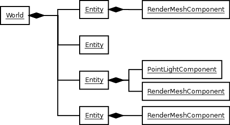
Broadly speaking the entity component model can be summarized as the following: An entity is composed of components who each serve a unique purpose. The entity does not contain any logic of its own but is empowered by said components.

Attached Image: ecm-intro.png

But what does the entity component model try to solve?

Each and every illustration of the entity component model starts with a classic object oriented conundrum: a deep inheritance hierarchy with orthogonal proposes. For example you have a Goblin class. You form two specialisations of the Goblin class, the FylingGoblin who can fly and the MagicGoblin who uses magic spells. The problem is that it is hard to create the FylingMagicGoblin.


Attached Image: dreaded-diamond.png


Even with C++ and its multiple inheritance, you are not in the clear as you still have the dreaded diamond and virtual inheritance to solve. But most languages simply do not support a concise way to implement it.

When solving the issue with components, the components GroundMovement, FlyingMovment, MeleAttack and MagicAttack are created and the different types of goblins are composed from these.


Attached Image: flying-magic-goblin.png


Good job, now we went from one anti-pattern (deep inheritance hierarchy) to a different anti-pattern (wide inheritance hierarchy). The central issue is that the inheritance hierarchy tries to incorporate orthogonal concepts and that is never a good idea. Why not have two object hierarchies, one for attack modes and one for movement modes?


Attached Image: goblin-sanity.png


As you can see from an object oriented standpoint the entity component model fares quite poorly. But that is not the only problem the entity component model tries to solve.

In many cases you see the concept of a data driven engine. The idea is that you can cut down on development time by moving the object composition out of the code and into some form of data. This allows game designers to "build" new objects by writing some XML or using a fancy editor. Although the underlying motivation is valid, it does not need to use an entity component model, as a few counter examples show quite well.

Putting the structural criticism aside, a naive implementation of the entity component model can in no way be efficient. In most cases the components are not such high concepts as moving or attacking, they are more along the lines of rendering and collision detection. But unless you have additional management structures, you need to look at each and every entity and check if it has components that are relevant for the rendering process.


Attached Image: inefficient.png


The simplest way to resolve the issue, without altering the design too radically, is the introduction of systems. In this case the actual implementation is within the systems and the components are just indicating the desired behaviour. The result is that a system has all the relevant data in a very concise and compact format and as a result can operate quite efficiently.


Attached Image: better-graphics.png


But if you look closely you can see that we have all these useless components. What if you removed the components and just used properties on the components and the systems just look for appropriately named properties? Now you have duck typing.


Attached Image: duck-typing.png


Duck typing is a concept that is used allot in weakly typed languages, like for example JavaScript or Python. The main idea here is that the actual type is irrelevant, but specific properties and function are expected on a given object within a specific context. For example it is irrelevant if it is a file stream, a memory stream or a network socket - if it has the write function it can be used to serialize objects to.

The problem with duck typing is that is does not lend itself easily to native languages. You can cook up some solution using some varying type but in no way is this an elegant solution.

Chances are you already have a scripting system, in this case the solution is quite straight forward, you implement the core game logic in scripts and underlying systems look at this definition and implement any heavy lifting in native code. The idea of alternating hard and soft layers is nothing new and should be considered where flexibility and performance is needed.

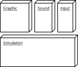
You may think that implementing the game logic in scripts is an inefficient way to do it. In cases where you are building a simulation-oriented game this may be quite true. In these cases is makes sense to extract your logic and reduce it to its core concepts, a simulaiton if you will. Then implement the presentation layer and control layers externally directly against the simulation layer.


Attached Image: totally-not-mvc.png


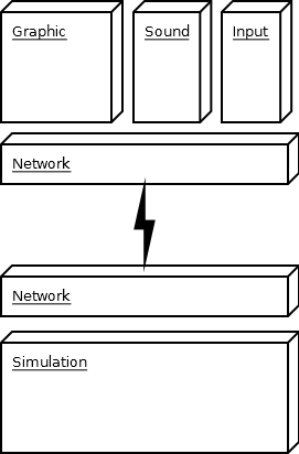
The nice thing about this design is that you can split the presentation layer and simulation so far that you can put one of them on one computer and the other on a different one.


Attached Image: mvc-network.png


Wait, did you just describe MVC? Um... No... Stop changing the subject.

When looking into scalability you get interesting requirements. One very clever implementation of the entity component system was make it scale in an MMO setting. The idea here is that entities and components do not exist in code, but are entries in a database. The systems are distributed over multiple computers and each work at their own pace and read and write to the dabase as required.


Attached Image: mmo-ecm.png


This design addresses the need of a distributed system and reminds me of the High Level Architecture][10] used by NASA and NATO to hook up multiple real-time simulations together. Yes this design approach even has its own standard, the IEEE 1516.

Ok, oh wise one, what should we do?

If you read about these issues you are either building a game engine or a game. Each and every game has different requirements and game engines try to satisfy a subset of these different requirements. Remember what you are developing and the scope of your requirements. If your current design sucks, you do not need to go overboard with your design, because chances are you aren't gonna need it. Try to make the smallest step that will solve the problem you are facing. It pays out to be creative and look at what others have done.

Entities-Parts II: Interactions

$
0
0
The previous article in the series, Game Objects, gave a broad overview of entities and parts, an implementation for the Entity and Part class, and a simple example showing a lopsided fight between a monster Entity and a helpless villager Entity. It was basic enough to demonstrate how to use the Entity and Part classes but it didn't address entity management or interaction in detail. In addition to addressing these topics, the example will be expanded so that the villager's friends will join the battle against a mob of monsters.

The previous article focused more on how entities and parts were structured. In this article, I will focus on ways to handle interactions between high-level classes, entities, and parts. Some examples of interactions are A.I. to target enemies or support allies, spell effects such as healing and summoning, and dealing damage to another character. I will also introduce a new class to the Entity-Parts framework: EntityManager, and an event system. The implementation of the framework will be provided in Java and C++ w/boost.

Handling Interactions


Interactions between Parts of the same Entity


Putting logic in parts is a good idea when you want to model interactions between parts of the same entity. For example, a part for health regeneration could simply get the health part of its parent entity and increase the health every update step. In the Entities-Parts framework you add logic to parts by overriding the initialize, update, or cleanup methods.

Interactions between Multiple Entities


Putting logic in high-level classes such as systems and managers is a good idea when you want to model interactions between entities. For example, an Entity such as a warrior will need a list of enemy entities to attack. Implementing all of this logic in parts is difficult because the parts would be responsible for finding references of enemy entities to damage. As seen in the previous article's MonsterControllerPart, it is difficult to pass in references to other entities to parts without issues appearing. A better approach is to have a high-level class, e.g. a BattleSystem, go through the list of all characters in the battle and find ones that are marked as enemies. It can then find a suitable enemy from the list and use the entity's weapon to deal damage to it.

Events


Events are commonly used in programming and are not restricted to games. They allow objects to immediately perform actions when something interesting happens. For example, when a missle receives a collision event, its collision event handler method makes it explode. In this fashion, the missle doesn't have to check each frame if it collided with anything, only when the collision happened. Events can sometimes simplify interactions between multiple objects.

Event managers allow an object to wait on a certain event to happen and then act upon it while being decoupled from objects publishing the event. An event manager is a centralized hub of event publication/subscription that allows entities or other systems to simply subscribe to the event manager instead of the individual objects who are publishing the events. Likewise, the publishers can just publish an event to the event manager and let the event manager do the work of notifying the subscribers of the event.

For example, the entity manager listens for an event where a new entity is created. If a new entity is spawned, say by a summon spell, the entity manager receives the event from the event manager and adds the new entity. It doesn't have to contain a reference to the summon spell.

RPG Battle Example (continued)


Now that we've discussed a high-level overview of handling interactions between high-level classes, entities, and parts, let's continue the example from the previous article.

The RPG Battle Example has been completely refactored to support a larger battle between two teams of characters: Monsters vs. Villagers. Each side will have a Meleer, Ranger, Flying Ranger, Support Mage, and Summoner. Monster names start with M. and villager names start with V. Here is output of a round of combat in the updated example. Each character's information is displayed as well as the action it took during the current simulation time:

SIMULATION TIME: 3.0
M.Meleer1 is dead!
M.Ranger1 - Health: 89.25 - Mana: 0.0
	Attacking with Bow.  34.0 damage dealt to V.Ranger1
M.FlyingRanger1 - Health: 100.0 - Mana: 0.0
	Attacking with Bow.  23.0 damage dealt to V.Ranger1
M.SupportMage1 - Health: 100.0 - Mana: 56.0
	Casting Light Heal.  Healed 30.0 health on M.Ranger1
M.Summoner1 - Health: 100.0 - Mana: 39.0
	Attacking with Staff.  14.0 damage dealt to V.Ranger1
V.Ranger1 - Health: 28.25 - Mana: 0.0
	Attacking with Bow.  29.0 damage dealt to M.Ranger1
V.FlyingRanger1 - Health: 100.0 - Mana: 0.0
	Attacking with Bow.  21.0 damage dealt to M.Ranger1
V.SupportMage1 - Health: 100.0 - Mana: 34.0
	Casting Light Heal.  Healed 30.0 health on V.Ranger1
V.Summoner1 - Health: 100.0 - Mana: 39.0
	Attacking with Staff.  12.0 damage dealt to M.Ranger1
Demon - Health: 100.0 - Mana: 0.0
	Attacking with Claw.  28.0 damage dealt to V.Ranger1
Demon - Health: 100.0 - Mana: 0.0
	Attacking with Claw.  21.0 damage dealt to M.Ranger1

Now, let's walk through key sections of the example code.

Character Creation


In the updated example, characters of differing roles are created using a CharacterFactory.

The following is a helper method to create a base/classless character. Note the parts that are added. They provide an empty entity with attributes that all characters should have such as name, health, mana, stat restoration, alliance (Monster or Villager), and mentality (how the AI reacts to certain situations).

	private static Entity createBaseCharacter(String name, float health, float mana, Alliance alliance, 
			Mentality mentality) {
		// create a character entity that has parts all characters should have
		Entity character = new Entity();
		character.attach(new DescriptionPart(name));
		character.attach(new HealthPart(health));
		character.attach(new ManaPart(mana));
		character.attach(new RestorePart(0.01f, 0.03f));
		character.attach(new AlliancePart(alliance));
		character.attach(new MentalityPart(mentality));
		return character;
	}

Then, there are methods for creating specific characters such as the flying ranger. The method to create the flying ranger calls createBaseCharacter method to create a base character with 100 health, 0 mana, and an Offensive Mentality that tells it to attack with its weapon and ignore defense or support. We add the equipment part with a bow weapon that does 15-35 damage and the flying part to make a base character a flying ranger. Note that weapons with an AttackRange of FAR can hit flying entities.

	public static Entity createFlyingRanger(String name, Alliance alliance) {
		Entity ranger = createBaseCharacter(name, 100, 0, alliance, Mentality.OFFENSIVE);
		Weapon bow = new Weapon("Bow", 15, 35, AttackRange.FAR);
		ranger.attach(new EquipmentPart(bow));
		ranger.attach(new FlyingPart());
		return ranger;
	}

As you can see, it is relatively easy to create numerous character roles or change existing character roles through reuse of parts. Take a look at the other CharacterFactory methods to see how other RPG classes are created.

Entity Management


The EntityManager is a centralized class for entity retrieval, addition, and removal from the game world. In the example, the EntityManager keeps track of the characters battling eachother. The list of characters is encapsulated in the Entity Manager to prevent it from being accidentally altered or replaced.

The game loop uses the entity manager to retrieve all the entities and update them. Then, update is called on the entityManager so that it updates its entity list according to recently created or removed entities.

Main.java:
			for (Entity entity : entityManager.getAll()) {
				entity.update(delta);
			}
			entityManager.update();

Events


To create a summoner with a summon spell, we need to find a way to notify the EntityManager that a new entity has been summoned so the EntityManager can add it to the battle. This can be accomplished with events. The EventManager is passed to the summon spell's use method and it calls the notify method on the EventManager to notify the EntitySystem to add the summoned Entity. In the entity manager's constructor, it called a method to listen for the EntityCreate event.

The classes that make up the event are the EntityCreateEvent and the EntityCreateListener. I didn't create the original event manager class so I can't take credit for it. See Event Manager for the original implementation and details on creating event listener and event classes.

Note: The C++ version of the EventManager works differently using function bindings instead of event listeners. The comments in the file 'EventManager.h' will show you how to use it.

Summon spell:
public class SummonSpell extends Spell {

	private Entity summon;
	
	public SummonSpell(String name, float cost, Entity summon) {
		super(name, cost);
		this.summon = summon;
	}

	public void use(EventManager eventManager) {
		HealthPart healthPart = summon.get(HealthPart.class);
		healthPart.setHealth(healthPart.getMaxHealth());
		eventManager.notify(new EntityCreatedEvent(summon));
		System.out.println("\tCasting " + name);
	}

}

Event for entity create:
public class EntityCreateEvent implements Event<EntityCreateListener> {

	private Entity entity;
	
	public EntityCreateEvent(Entity entity) {
		this.entity = entity;
	}
	
	@Override
	public void notify(EntityCreateListener listener) {
		listener.create(entity);
	}
	
}

EventListener for entity created:
public interface EntityCreateListener {

	public void create(final Entity entity);
	
}

Stat Restoration


In the example, characters regenerate health each timestep. The RestorePart increases the health and mana of its parent Entity every time its update method is called. As you can see, it interacts with other parts and updates their state.

public class RestorePart extends Part {
	
	private float healthRestoreRate;
	private float manaRestoreRate;

	public RestorePart(float healthRestoreRate, float manaRestoreRate) {
		this.healthRestoreRate = healthRestoreRate;
		this.manaRestoreRate = manaRestoreRate;
	}
	
	@Override
	public void update(float dt) {
		HealthPart healthPart = getEntity().get(HealthPart.class);
		float newHealth = calculateRestoredValue(healthPart.getMaxHealth(), healthPart.getHealth(), healthRestoreRate * dt);
		healthPart.setHealth(newHealth);
		
		ManaPart manaPart = getEntity().get(ManaPart.class);
		float newMana = calculateRestoredValue(manaPart.getMaxMana(), manaPart.getMana(), manaRestoreRate * dt);
		manaPart.setMana(newMana);
	}
	
	private float calculateRestoredValue(float maxValue, float currentValue, float restoreRate) {
		float manaRestoreAmount = maxValue * restoreRate;
		float maxManaRestoreAmount = Math.min(maxValue - currentValue, manaRestoreAmount);
		float newMana = currentValue + maxManaRestoreAmount;
		return newMana;
	}
	
}

Battle System


The BattleSystem is where high-level interactions between entities are implemented, e.g. targeting and intelligence. It also contains rules of the game such as when an entity is considered dead. In the future, we might want to create an AI System to handle targeting and just have the Battle System control the rules of the game. But, for a simple example it's fine as it is.

In the following code snippet of the BattleSystem, note that it is using each character's Mentality part to specify how it will act in the current turn. The BattleSystem also resolves the issue from the last example of providing potential targets for attacking and supporting.

	public void act(Entity actingCharacter, List<Entity> characters) {
		Mentality mentality = actingCharacter.get(MentalityPart.class).getMentality();
		
		if (mentality == Mentality.OFFENSIVE) {
			attemptAttack(actingCharacter, characters);
		}
		else if (mentality == Mentality.SUPPORT) {
			boolean healed = attemptHeal(actingCharacter, characters);
			if (!healed) {
				attemptAttack(actingCharacter, characters);
			}
		}
		else if (mentality == Mentality.SUMMON) {
			boolean summoned = attemptSummon(actingCharacter);
			if (!summoned) {
				attemptAttack(actingCharacter, characters);
			}
		}
	}

In addition to managing AI, it contains the game rules, such as when a character should be removed from the game using the helper method isAlive and the EntityManager remove method.

		for (Entity character : characters) {
			if (!isAlive(character)) {
				entityManager.remove(character);
				System.out.println(character.get(DescriptionPart.class).getName() + " is dead!");
			}

Conclusion


Handling interactions between entities can become complex in large-scale games. I hope this article was helpful in providing several approaches to interactions by using high-level classes, adding logic to parts, and using events.

The first and second articles addressed the core of creating and using entities and parts. If you want, take a closer look at of the example code or change it to get a feel of how it manages interactions between entities.

Though the CharacterFactory is fine for small and medium-sized games, it doesn't scale well for large games where potentially thousands of game object types exist. The next article will describe several approaches to mass creation of game object types using data files and serialization.

Article Update Log


16 April 2014: Initial release

Hacking the monolithic entity system

$
0
0
Hi and welcome back! This time I’m going to talk about a trick I used on the old PS2 game ’24 The Game’ to save over 30% of a frame by hacking the game’s monolithic entity system.

The monolithic entity system


You’ve probably all seen this design before:

  1. Entity manager, stores a list of all entities
  2. Each entity implements an Update() function
  3. Every frame, the manager loops through all entities and calls Update() on each one

The primary problem with this design is it’s polling nature; each entity is polled to do work, even when that entity may not have any work to do. This doesn’t start out being a problem at the beginning of the development of a game when there are only a handful of entities, but it sure is when the game is full of 1000s of them!

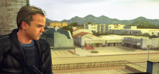
In ’24 The Game’, entities were any object which you could interact with, which included: doors, characters, cars, guns, pick-ups, boxes and any other physics objects. They soon started stacking up in numbers, especially when you consider the game’s draw distance.


Attached Image: 24_Snipe_4_3.jpg


Event driven


In an ideal world, the system wouldn’t have been designed like this in the first place. Something event driven would have been more appropriate for the majority of entities – so entities just sleep until they are acted upon by an incoming event, such as being shot, or collided with. While asleep an entity would have done no work and therefore taken no CPU time.

However, this was not to be since the game was in beta and rewriting the entire entity system seemed like a bad idea(!)

Hacking the monolithic entity system


So a more achievable method was needed, one which could be plugged right into the existing system without breaking everything.

The solution was discovered after making a key observation about the nature of the variable time-step we were already using in game.

In a game where the time-step varies from frame to frame (like nearly every game in the world), entities must adjust their behaviour to cope with a differing frame rate – for example, animations move forward a differing number of frames, characters move across the ground differing amounts per frame and so on.

This being the case, calling Update() on ‘unimportant’ entities every 2nd or 4th frame wouldn’t break anything and would save a bunch of CPU time.

Unimportant entities


So, what is an unimportant entity? From the point of view of this system, an unimportant entity is one which is not currently interacting with the player, or is very small on screen, or completely off-screen.

Mitigating edge cases


Unimportant entities could temporarily have their importance increased after receiving an event, such as being shot, or collided with. This mitigated the problem of ‘dumb entities’ which would take a long time to react to events in this new system.

Screen-space size should be used rather than just plain distance when calculating importance, otherwise zooming in on a far away moving character would reveal jerky animation, as the animation controller only got updated every other frame.

Importance overrides will always be needed in some cases, like if you have a bunch of AI companion team-mates who are following behind the player.

Very unimportant entities could volunteer themselves to be excluded from Update() completely if they did no work there, such as most physics objects.

Results


In the end this system saved 30% of a frame in general across all levels, sometimes a lot more which was a definite result. However, if possible don’t design a monolithic system in the first place!

That’s all folks

Thanks for reading, hope this post gives you some ideas! For more ideas check out my blog at http://www.wildbunny.co.uk/blog/.


Article Update Log


10 Aprl 2014: Initial release

A Long-Awaited Check of Unreal Engine 4

$
0
0
On March 19, 2014, Unreal Engine 4 was made publicly available. Subscription costs only $19 per month. The source codes have also been published at the github repository. Since that moment, we have received quite a number of e-mails, twitter messages, etc., people asking to check this game engine. So we are fulfilling our readers' request in this article; let's see what interesting bugs the PVS-Studio static code analyzer has found in the project's source code.

image1.png

Unreal Engine


The Unreal Engine is a game engine developed by Epic Games, first illustrated in the 1998 first-person shooter game Unreal. Although primarily developed for the first-person shooters, it has been successfully used in a variety of other genres, including stealth, MMORPGs, and other RPGs. With its code written in C++, Unreal Engine features a high degree of portability and is a tool used by many game developers today.

The official website: https://www.unrealengine.com/

The Wikipedia article: Unreal Engine.

Analysis methodology for an nmake-based project


There exist certain difficulties regarding analysis of the Unreal Engine project. To check it, we had to use a new feature recently introduced in PVS-Studio Standalone. Because of that, we had to postpone the publication of this article a bit so that it would follow the release of the new PVS-Studio version with this feature. I guess many would like to try it: it allows programmers to easily check projects that make use of complex or non-standard build systems.

PVS-Studio's original working principle is as follows:
  • You open a project in Visual Studio.
  • Click the "Start" button.
  • The Visual Studio-integrated plugin collects all the necessary information: which files need to be analyzed, which macros are to be expanded, where the header files location, and so on.
  • The plugin launches the analyzer module itself and outputs the analysis results.
What's special about Unreal Engine 4 is that it is an nmake-based project, therefore it can't be checked by the PVS-Studio plugin.

Let me explain this point. Unreal Engine is implemented as a Visual Studio project, but the build is done with nmake. It means that the plugin cannot know which files are compiled with which switches. Therefore, analysis is impossible. To be exact, it is possible, but it will be somewhat of an effort (see the documentation section, "Direct integration of the analyzer into build automation systems").

And here's PVS-Studio Standalone coming to help! It can work in two modes:

  1. You obtain preprocessed files in any way and let the tool check them.
  2. Its monitoring compiler calls and get all the necessary information.

It is the second mode that we are interested in now. This is how the check of Unreal Engine was done:

  1. We launched PVS-Studio Standalone.
  2. Clicked "Compiler Monitoring".
  3. Then we clicked "Start Monitoring" and made sure the compiler call monitoring mode was on.
  4. We opened the Unreal Engine project in Visual Studio and started the project build. The monitoring window indicated that the compiler calls were being tapped.
  5. When the build was finished, we clicked Stop Monitoring, and after that the PVS-Studio analyzer was launched.

The diagnostic messages were displayed in the PVS-Studio Standalone window.

Hint. It is more convenient to use Visual Studio instead of the PVS-Studio Standalone's editor to work with the analysis report. You only need to save the results into a log file and then open it in the Visual Studio environment (Menu->PVS-Studio->Open/Save->Open Analysis Report).

All that and many other things are described in detail in the article "PVS-Studio Now Supports Any Build System under Windows and Any Compiler. Easy and Right Out of the Box". Do read this article please before you start experimenting with PVS-Studio Standalone!

Analysis results


I found the Unreal Engine project's code very high-quality. For example, developers employ static code analysis during the development, which is hinted at by the following code fragments:

// Suppress static code analysis warning about a
// potential comparison of two constants
CA_SUPPRESS(6326);
....
// Suppress static code analysis warnings about a
// potentially ill-defined loop. BlendCount > 0 is valid.
CA_SUPPRESS(6294)
....
#if USING_CODE_ANALYSIS

These code fragments prove that they use a static code analyzer integrated into Visual Studio. To find out more about this tool, see the article Visual Studio 2013 Static Code Analysis in depth: What? When and How?

The project authors may also use some other analyzers, but I can't say for sure.

So their code is pretty good. Since they use static code analysis tools during the development, PVS-Studio has not found many suspicious fragments. However, just like any other large project, this one does have some bugs, and PVS-Studio can catch some of them. So let's find out what it has to show us.

Typos


static bool PositionIsInside(....)
{
  return
    Position.X >= Control.Center.X - BoxSize.X * 0.5f &&
    Position.X <= Control.Center.X + BoxSize.X * 0.5f &&
    Position.Y >= Control.Center.Y - BoxSize.Y * 0.5f &&
    Position.Y >= Control.Center.Y - BoxSize.Y * 0.5f;
}

PVS-Studio's diagnostic message: V501 There are identical sub-expressions 'Position.Y >= Control.Center.Y - BoxSize.Y * 0.5f' to the left and to the right of the '&&' operator. svirtualjoystick.cpp 97

Notice that the Position.Y variable is compared to the Control.Center.Y - BoxSize.Y * 0.5f expression twice. This is obviously a typo; the '-' operator should be replaced with '+' in the last line.

Here's one more similar mistake in a condition:

void FOculusRiftHMD::PreRenderView_RenderThread(
  FSceneView& View)
{
  ....
  if (View.StereoPass == eSSP_LEFT_EYE ||
      View.StereoPass == eSSP_LEFT_EYE)
  ....
}

PVS-Studio's diagnostic message: V501 There are identical sub-expressions 'View.StereoPass == eSSP_LEFT_EYE' to the left and to the right of the '||' operator. oculusrifthmd.cpp 1453

It seems that the work with Oculus Rift is not well tested yet.

Let's go on.

struct FMemoryAllocationStats_DEPRECATED
{
  ....
  SIZE_T  NotUsed5;
  SIZE_T  NotUsed6;
  SIZE_T  NotUsed7;
  SIZE_T  NotUsed8;
  ....
};

FMemoryAllocationStats_DEPRECATED()
{
  ....
  NotUsed5 = 0;
  NotUsed6 = 0;
  NotUsed6 = 0;  
  NotUsed8 = 0;  
  ....
}

PVS-Studio's diagnostic message: V519 The 'NotUsed6' variable is assigned values twice successively. Perhaps this is a mistake. Check lines: 86, 88. memorybase.h 88

Structure members are initialized here. A typo causes the NotUsed6 member to be initialized twice, while the NotUsed7 member remains uninitialized. However, the _DEPRECATED() suffix in the function name tells us this code is not of much interest anymore.

Here are two other fragments where one variable is assigned a value twice:
  • V519 The HighlightText variable is assigned values twice successively. Perhaps this is a mistake. Check lines: 204, 206. srichtextblock.cpp 206
  • V519 The TrackError.MaxErrorInScaleDueToScale variable is assigned values twice successively. Perhaps this is a mistake. Check lines: 1715, 1716. animationutils.cpp 1716

Null pointers


I pretty often come across null pointer dereferencing errors in error handlers. No wonder: these fragments are difficult and uninteresting to test. In Unreal Engine, you can find a null pointer dereferencing error in an error handler too:

bool UEngine::CommitMapChange( FWorldContext &Context )
{
  ....
  LevelStreamingObject = Context.World()->StreamingLevels[j];
  if (LevelStreamingObject != NULL)
  {
    ....
  }
  else
  {
    check(LevelStreamingObject);
    UE_LOG(LogStreaming, Log,
           TEXT("Unable to handle streaming object %s"),
           *LevelStreamingObject->GetName());
  }
  ....
}

PVS-Studio's diagnostic message: V522 Dereferencing of the null pointer 'LevelStreamingObject' might take place. unrealengine.cpp 10768

We want to print the object name when an error occurs. But the object doesn't exist.

Here's another fragment with null pointer dereferencing. It's all much more interesting here. Perhaps the error appeared because of an incorrect merge. Anyway, the comment proves that the code is incomplete:

void FStreamingPause::Init()
{
  ....
  if( GStreamingPauseBackground == NULL && GUseStreamingPause )
  {
    // @todo UE4 merge andrew
    // GStreamingPauseBackground = new FFrontBufferTexture(....);
    GStreamingPauseBackground->InitRHI();
  }
}

PVS-Studio's diagnostic message: V522 Dereferencing of the null pointer 'GStreamingPauseBackground' might take place. streamingpauserendering.cpp 197

A few more words about null pointers


Almost in every program I check, I get a pile of V595 warnings (examples). These warnings indicate the following trouble:

A pointer is dereferenced first and only then is checked for being null. That's not always an error, but this code is highly suspicious and needs to be checked anyway!

The V595 diagnostic helps us reveal slip-ups like this:

/**
 * Global engine pointer.
 * Can be 0 so don't use without checking.
 */
ENGINE_API UEngine* GEngine = NULL;

bool UEngine::LoadMap( FWorldContext& WorldContext,
  FURL URL, class UPendingNetGame* Pending, FString& Error )
{
  ....
  if (GEngine->GameViewport != NULL)
  {
    ClearDebugDisplayProperties();
  }

  if( GEngine )
  {
    GEngine->WorldDestroyed( WorldContext.World() );
  }
  ....
}

PVS-Studio's diagnostic message: V595 The 'GEngine' pointer was utilized before it was verified against nullptr. Check lines: 9714, 9719. unrealengine.cpp 9714

Notice the comment. The global variable GEngine may be equal to zero, so it must be checked before it can be used.

And there is such a check indeed in the function LoadMap():

if( GEngine )

Unfortunately, this check is executed only after the pointer has been already used:

if (GEngine->GameViewport != NULL)

There were quite a number of V595 warnings for the project (about 82). I guess many of them are false positives, so I won't litter the article with the samples and cite them in a separate list: ue-v595.txt.

Excess variable declaration


This error is pretty nice. It is about mistakenly declaring a new variable instead of using an already existing one.

void FStreamableManager::AsyncLoadCallback(....)
{
  ....
  FStreamable* Existing = StreamableItems.FindRef(TargetName);
  ....
  if (!Existing)
  {
    // hmm, maybe it was redirected by a consolidate
    TargetName = ResolveRedirects(TargetName);
    FStreamable* Existing = StreamableItems.FindRef(TargetName);
  }
  if (Existing && Existing->bAsyncLoadRequestOutstanding)
  ....
}

PVS-Studio's diagnostic message: V561 It's probably better to assign value to 'Existing' variable than to declare it anew. Previous declaration: streamablemanager.cpp, line 325. streamablemanager.cpp 332

I suspect the code must look like this:

// hmm, maybe it was redirected by a consolidate
TargetName = ResolveRedirects(TargetName);
Existing = StreamableItems.FindRef(TargetName);

Errors in function calls


bool FRecastQueryFilter::IsEqual(
  const INavigationQueryFilterInterface* Other) const
{
  // @NOTE: not type safe, should be changed when
  // another filter type is introduced
  return FMemory::Memcmp(this, Other, sizeof(this)) == 0;
}

PVS-Studio's diagnostic message: V579 The Memcmp function receives the pointer and its size as arguments. It is possibly a mistake. Inspect the third argument. pimplrecastnavmesh.cpp 172

The comment warns us that it is dangerous to use Memcmp(). But actually it all is even worse than the programmer expects. The point is that the function compares only a part of the object.

The sizeof(this) operator returns the pointer size; that is, the function will compare the first 4 bytes in a 32-bit program and 8 bytes in a 64-bit program.

The correct code should look as follows:

return FMemory::Memcmp(this, Other, sizeof(*this)) == 0;

But that's not the only trouble with the Memcmp() function. Have a look at the following code fragment:

D3D11_STATE_CACHE_INLINE void GetBlendState(
  ID3D11BlendState** BlendState, float BlendFactor[4],
  uint32* SampleMask)
{
  ....
  FMemory::Memcmp(BlendFactor, CurrentBlendFactor,
                  sizeof(CurrentBlendFactor));
  ....
}

PVS-Studio's diagnostic message: V530 The return value of function 'Memcmp' is required to be utilized. d3d11statecacheprivate.h 547

The analyzer was surprised at finding the Memcmp() function's result not being used anywhere. And this is an error indeed. As far as I get it, the programmer wanted to copy the data, not compare them. If so, the Memcpy() function should be used:

FMemory::Memcpy(BlendFactor, CurrentBlendFactor,
                sizeof(CurrentBlendFactor));

A variable assigned to itself


enum ECubeFace;
ECubeFace CubeFace;

friend FArchive& operator<<(
  FArchive& Ar,FResolveParams& ResolveParams)
{
  ....
  if(Ar.IsLoading())
  {
    ResolveParams.CubeFace = (ECubeFace)ResolveParams.CubeFace;
  }
  ....
}

PVS-Studio's diagnostic message: V570 The 'ResolveParams.CubeFace' variable is assigned to itself. rhi.h 1279

The ResolveParams.CubeFace variable is of the ECubeFace type, and it is cast explicitly to the ECubeFace type, i.e. nothing happens. After that, the variable is assigned to itself. Something is wrong with this code.

The nicest of all the errors


image2.png
I do like the following error most of all:

bool VertInfluencedByActiveBone(
  FParticleEmitterInstance* Owner,
  USkeletalMeshComponent* InSkelMeshComponent,
  int32 InVertexIndex,
  int32* OutBoneIndex = NULL);

void UParticleModuleLocationSkelVertSurface::Spawn(....)
{
  ....
  int32 BoneIndex1, BoneIndex2, BoneIndex3;
  BoneIndex1 = BoneIndex2 = BoneIndex3 = INDEX_NONE;

  if(!VertInfluencedByActiveBone(
        Owner, SourceComponent, VertIndex[0], &BoneIndex1) &&
     !VertInfluencedByActiveBone(
        Owner, SourceComponent, VertIndex[1], &BoneIndex2) && 
     !VertInfluencedByActiveBone(
        Owner, SourceComponent, VertIndex[2]) &BoneIndex3)
  {
  ....
}

PVS-Studio's diagnostic message: V564 The '&' operator is applied to bool type value. You've probably forgotten to include parentheses or intended to use the '&&' operator. particlemodules_location.cpp 2120

It's not that easy to spot it. I'm sure you've just scanned through the code and haven't noticed anything strange. The analyzer warning, unfortunately, is also strange and suggests a false positive. But in fact, we are dealing with a real and very interesting bug.

Let's figure it all out. Notice that the last argument of the VertInfluencedByActiveBone() function is optional.

In this code fragment, the VertInfluencedByActiveBone() function is called 3 times. The first two times, it receives 4 arguments; with the last call, only 3 arguments. And here is where the error is lurking.

It is only from pure luck that the code compiles well, the error staying unnoticed. This is how it happens:

  1. The function is called with 3 arguments: VertInfluencedByActiveBone(Owner, SourceComponent, VertIndex[2]);
  2. The '!' operator is applied to the function result;
  3. The !VertInfluencedByActiveBone(...) expression evaluates to a bool value;
  4. The '&' (bitwise AND) operator is applied to it;
  5. All this is compiled successfully because there is a bool expression to the left of the '&' operator and an integer variable BoneIndex3 to the right.

The analyzer suspected something was wrong on discovering one of the '&' operator's arguments to have the bool type. And that was what it warned us about - not in vain.

To fix the error, we need to add a comma and put a closing parenthesis in the right place:

if(!VertInfluencedByActiveBone(
      Owner, SourceComponent, VertIndex[0], &BoneIndex1) &&
   !VertInfluencedByActiveBone(
      Owner, SourceComponent, VertIndex[1], &BoneIndex2) && 
   !VertInfluencedByActiveBone(
      Owner, SourceComponent, VertIndex[2], &BoneIndex3))

A break operator missing


static void VerifyUniformLayout(....)
{
  ....
  switch(Member.GetBaseType())
  {
    case UBMT_STRUCT:  BaseTypeName = TEXT("struct"); 
    case UBMT_BOOL:    BaseTypeName = TEXT("bool"); break;
    case UBMT_INT32:   BaseTypeName = TEXT("int"); break;
    case UBMT_UINT32:  BaseTypeName = TEXT("uint"); break;
    case UBMT_FLOAT32: BaseTypeName = TEXT("float"); break;
    default:           
      UE_LOG(LogShaders, Fatal,
        TEXT("Unrecognized uniform ......"));
  };
  ....
}

PVS-Studio's diagnostic message: V519 The 'BaseTypeName' variable is assigned values twice successively. Perhaps this is a mistake. Check lines: 862, 863. openglshaders.cpp 863

The break; operator is missing in the very beginning. I guess no comments and explanations are needed.

Microoptimizations


The PVS-Studio analyzer offers a small set of diagnostic rules that help carry out microoptimizations of the code. Though small, they may prove pretty useful at times. Let's take one assignment operator as an example:

FVariant& operator=( const TArray<uint8> InArray )
{
  Type = EVariantTypes::ByteArray;
  Value = InArray;
  return *this;
}

PVS-Studio's diagnostic message: V801 Decreased performance. It is better to redefine the first function argument as a reference. Consider replacing 'const .. InArray' with 'const .. &InArray'. variant.h 198

It's not a very good idea to pass an array by value. The InArray can and must be passed by a constant reference.

The analyzer generated quite a few warnings related to microoptimizations. I don't think many of them will be really useful, but here you are a list of these fragments just in case: ue-v801-V803.txt.

Suspicious sum


uint32 GetAllocatedSize() const
{
  return UniformVectorExpressions.GetAllocatedSize()
    + UniformScalarExpressions.GetAllocatedSize()
    + Uniform2DTextureExpressions.GetAllocatedSize()
    + UniformCubeTextureExpressions.GetAllocatedSize()
    + ParameterCollections.GetAllocatedSize()
    + UniformBufferStruct
        ?
        (sizeof(FUniformBufferStruct) +
         UniformBufferStruct->GetMembers().GetAllocatedSize())
        :
        0;
}

PVS-Studio's diagnostic message: V502 Perhaps the '?:' operator works in a different way than it was expected. The '?:' operator has a lower priority than the '+' operator. materialshared.h 224

This code is pretty complicated. To make the explanation clearer, I have composed a simplified artificial sample:

return A() + B() + C() + uniform ? UniformSize() : 0;

A certain size is being calculated in this code. Depending on the value of the uniform variable, either UniformSize() or 0 should be added. But the code actually works in quite a different way. The priority of the addition operators '+' is higher than that of the '?:' operator.

So here's what we get:

return (A() + B() + C() + uniform) ? UniformSize() : 0;

A similar issue can be found in Unreal Engine's code. I suspect the program calculates something different than the programmer wanted it to.

Mess-up with enum


I didn't feel like describing this case at first as I would have to cite quite a large piece of code. But then I overcame my laziness, so please be patient too.

namespace EOnlineSharingReadCategory
{
  enum Type
  {
    None          = 0x00,
    Posts         = 0x01,
    Friends       = 0x02,
    Mailbox       = 0x04,
    OnlineStatus  = 0x08,
    ProfileInfo   = 0x10,  
    LocationInfo  = 0x20,
    Default       = ProfileInfo|LocationInfo,
  };
}

namespace EOnlineSharingPublishingCategory
{
  enum Type {
    None          = 0x00,
    Posts         = 0x01,
    Friends       = 0x02,
    AccountAdmin  = 0x04,
    Events        = 0x08,
    Default       = None,
  };

  inline const TCHAR* ToString
    (EOnlineSharingReadCategory::Type CategoryType)
  {
    switch (CategoryType)
    {
    case None:
    {
      return TEXT("Category undefined");
    }
    case Posts:
    {
      return TEXT("Posts");
    }
    case Friends:
    {
      return TEXT("Friends");
    }
    case AccountAdmin:
    {
      return TEXT("Account Admin");
    }
    ....
  }
}

The analyzer generates a few V556 warnings at once on this code. The reason is that the switch operator has a variable of the EOnlineSharingReadCategory::Type type as its argument. At the same time, case operators work with values of a different type, EOnlineSharingPublishingCategory::Type.

A logical error


const TCHAR* UStructProperty::ImportText_Internal(....) const
{
  ....
  if (*Buffer == TCHAR('\"'))
  {
    while (*Buffer && *Buffer != TCHAR('\"') &&
           *Buffer != TCHAR('\n') && *Buffer != TCHAR('\r'))
    {
      Buffer++;
    }

    if (*Buffer != TCHAR('\"'))
  ....
}

PVS-Studio's diagnostic message: V637 Two opposite conditions were encountered. The second condition is always false. Check lines: 310, 312. propertystruct.cpp 310

The programmer intended to skip all text in double quotes. The algorithm was meant to be like this:
  • Once the program comes across a double quote, a loop is started.
  • The loop keeps skipping characters until stumbling across the next double quote.
The error is about the pointer failing to be referenced to the next character after the first double quote is found. As a result, the second double quote is found right away, too, and the loop doesn't start.

Here is simpler code to clarify the point:

if (*p == '\"')
{
  while (*p && *p != '\"')
      p++;
}

To fix the error, you need to change the code in the following way:

if (*p == '\"')
{
  p++;
  while (*p && *p != '\"')
      p++;
}

Suspicious shift


class FMallocBinned : public FMalloc
{
  ....
  /* Used to mask off the bits that have been used to
     lookup the indirect table */
  uint64 PoolMask;
  ....
  FMallocBinned(uint32 InPageSize, uint64 AddressLimit)
  {
    ....
    PoolMask = ( ( 1 << ( HashKeyShift - PoolBitShift ) ) - 1 );
    ....
  }
}

PVS-Studio's diagnostic message: V629 Consider inspecting the '1 < (HashKeyShift - PoolBitShift)' expression. Bit shifting of the 32-bit value with a subsequent expansion to the 64-bit type. mallocbinned.h 800

Whether or not this code contains an error depends on whether the value 1 needs to be shifted by more than 31 bits. Since the result is saved into a 64-bit variable PoolMask, it seems highly probable.

If I am right, the library contains an error in the memory allocation subsystem.

The number 1 is of the int type, which means that you cannot shift it by 35 bits, for example. Theoretically, it leads to undefined behavior (find out more). In practice, an overflow will occur and an incorrect value will be computed.

The fixed code looks as follows:

PoolMask = ( ( 1ull << ( HashKeyShift - PoolBitShift ) ) - 1 );

Obsolete checks


void FOculusRiftHMD::Startup()
{
  ....
  pSensorFusion = new SensorFusion();
  if (!pSensorFusion)
  {
    UE_LOG(LogHMD, Warning,
      TEXT("Error creating Oculus sensor fusion."));
    return;
  }
  ....
}

PVS-Studio's diagnostic message: V668 There is no sense in testing the 'pSensorFusion' pointer against null, as the memory was allocated using the 'new' operator. The exception will be generated in the case of memory allocation error. oculusrifthmd.cpp 1594

For a long time now the new operator has been throwing an exception in case of a memory allocation error. The if (!pSensorFusion) check is not needed.

I usually find quite a lot of such fragments in large projects, but Unreal Engine's code contains surprisingly few of them: ue-V668.txt.

Copy-Paste


The code fragments below have most likely appeared through the Copy-Paste method. Regardless of the condition, one and the same code branch is executed:

FString FPaths::CreateTempFilename(....)
{
  ....  
  const int32 PathLen = FCString::Strlen( Path );
  if( PathLen > 0 && Path[ PathLen - 1 ] != TEXT('/') )
  {
    UniqueFilename =
      FString::Printf( TEXT("%s/%s%s%s"), Path, Prefix,
                       *FGuid::NewGuid().ToString(), Extension );
  }
  else
  {
    UniqueFilename =
      FString::Printf( TEXT("%s/%s%s%s"), Path, Prefix,
                       *FGuid::NewGuid().ToString(), Extension );
  }
  ....
}

PVS-Studio's diagnostic message: V523 The 'then' statement is equivalent to the 'else' statement. paths.cpp 703

One more example:

template< typename DefinitionType >            
FORCENOINLINE void Set(....)
{
  ....
  if ( DefinitionPtr == NULL )
  {
    WidgetStyleValues.Add( PropertyName,
      MakeShareable( new DefinitionType( InStyleDefintion ) ) );
  }
  else
  {
    WidgetStyleValues.Add( PropertyName,
      MakeShareable( new DefinitionType( InStyleDefintion ) ) );
  }
}

PVS-Studio's diagnostic message: V523 The 'then' statement is equivalent to the 'else' statement. slatestyle.h 289

Miscellaneous


What's left is just diverse subtle issues which are not very interesting to discuss. So let me just cite a few code fragments and corresponding diagnostic messages.

void FNativeClassHeaderGenerator::ExportProperties(....)
{
  ....
  int32 NumByteProperties = 0;
  ....
  if (bIsByteProperty)
  {
    NumByteProperties;
  }
  ....
}

PVS-Studio's diagnostic message: V607 Ownerless expression 'NumByteProperties'. codegenerator.cpp 633

static void GetModuleVersion( .... )
{
  ....
  char* VersionInfo = new char[InfoSize];
  ....
  delete VersionInfo;
  ....
}

PVS-Studio's diagnostic message: V611 The memory was allocated using 'new T[]' operator but was released using the 'delete' operator. Consider inspecting this code. It's probably better to use 'delete [] VersionInfo;'. windowsplatformexceptionhandling.cpp 107

const FSlateBrush* FSlateGameResources::GetBrush(
  const FName PropertyName, ....)
{
  ....
  ensureMsgf(BrushAsset, TEXT("Could not find resource '%s'"),
             PropertyName);
  ....
}

PVS-Studio's diagnostic message: V510 The 'EnsureNotFalseFormatted' function is not expected to receive class-type variable as sixth actual argument. slategameresources.cpp 49

Conclusions


Using the static analyzer integrated into Visual Studio does make sense but it is not enough. The authors should consider using specialized tools in addition to it, for example our analyzer PVS-Studio. If you compare PVS-Studio to VS2013's analyzer, the former detects 6 times more bugs. Here you have the proof:

  1. Comparison of static code analyzers: CppCat, Cppcheck, PVS-Studio and Visual Studio;
  2. Comparison methodology.

I invite all those who want their code to be high-quality to try our code analyzer.

P.S. I should also mention that the errors described in this article (except for microoptimizations) could theoretically have been found by the lightweight analyzer CppCat as well. A one-year license for CppCat costs $250; annual renewal costs $200. But it wouldn't do in this particular case because it is lightweight and lacks the necessary functionality to monitoring compiler launches, which is a crucial requirement when checking Unreal Engine. However, the CppCat analyzer may well satisfy the authors of small projects.

Animating Characters with DirectX

$
0
0
DirectX 9 is good! It allows you to import .x files into your game projects unlike newer versions of DirectX. Why not ask yourself, "What do I want in my game?" well, the answer for me is 3D game characters and a nice 3D scene. I am writing this tutorial so that you may follow the steps required to create such a scene. Well at least the characters. I’ll leave the scene up to you. The scene will serve as an area for our characters to walk around. Unfortunately 3D studio max is not free for many people. I have no answer for this because I was unsuccessful in using Blender for animations; maybe now that I have experience I'd manage however if you are able to get hold of max, then great! There's nothing stopping you. There are plugin exporters available that do the job. And the aim of this tutorial is purely for teaching you how to create 3D DirectX games using any of the exporters available and as a refresher course for myself. DirectX is not easy but it is a lot of fun. So let's get started!

Note:  If you are familiar with the basics of setting up DirectX and Win32 applications, then you can skip straight to discussions of loading and animating models


Setting up Direct3D


Note:  if you are using a unicode character set for your projects, be sure to place an L before strings e.g. L"my string";


Let's start from the beginning: Creating a window. Setup a new empty Win32 project in Visual Studio; you will need a version of the DirectX SDK and to link in the include and library directories of the SDK into your project. This is done via project properties. In the linker->Input Additional dependencies add d3d9.lib and d3dx9.lib.

First we will include <windows.h> and create a WinMain() function and a Windows procedure WinProc(). WinMain is the entry point of the program that is executed first in a standard Windows application. Our WinMain function is outlined as:

int WINAPI WinMain(HINSTANCE hInstance, HINSTANCE hPrevInstance, PSTR cmdLine, int showCmd);

And the outline of our WndProc is:

LRESULT CALLBACK WndProc(HWND hWnd, UINT msg, WPARAM wParam, LPARAM lParam);

Place these declarations at the top of the cpp file after includes so that they can be referenced throughout other functions.

Now we will want an object to handle various application events such as game initialization, updating the game and cleaning of resources. We will create a simple Game object for this. Within the Init() function we will create a window and hold a handle to it, m_mainWindow:

class Game{
public:
	Game();
	~Game();

	HRESULT Init(HINSTANCE hInstance);
	void Update(float deltaTime);
	void Cleanup();
	
private:
	HWND m_mainWindow;
};

Don't forget the semi-colon after class declaration.

We create the window class that describes our window and register it with the operating system in the Game::Init() function. We will use a basic window class for this:

	WNDCLASS wc;
	//Prepare class for use
	memset(&wc, 0, sizeof(WNDCLASS));
	
	wc.style=CS_HREDRAW | CS_VREDRAW; //Redraws the window if width or height changes.
	//Associate the window procedure with the window
	wc.lpfnWndProc=(WNDPROC)WndProc;

	wc.hInstance=hInstance;
	wc.lpszClassName="Direct3D App";

Register the window class with the OS:

	if(FAILED(RegisterClass(&wc))){
		return E_FAIL;
	}

And finally, create the window; We use WS_OVERLAPPEDWINDOW for a standard minimize, maximize and close options:

m_mainWindow = CreateWindow("Direct3D App", //The window class to use
			      "Direct3D App", //window title
			      WS_OVERLAPPEDWINDOW, //window style
			      200, //x
			      200, //y
			      CW_USEDEFAULT, //Default width
			      CW_USEDEFAULT, //Default height
			      NULL, //Parent Window
			      NULL, //Menu
			      hInstance, //Application instance
			      0); //Pointer to value parameter, lParam of WndProc
if(!m_mainWindow){return E_FAIL;}
	And after CreateWindow, add:
ShowWindow(m_mainWindow, SW_SHOW);
UpdateWindow(m_mainWindow);

//Function completed successfully
return S_OK;

In the WinMain function we must create an instance of Game and call the Init function to initialize the window:

	Game mygame;

	if(FAILED(mygame.Init(hInstance))){
		MessageBox(NULL, "Failed to initialize game", NULL, MB_OK);
		return 1;
	}

Every Windows application has a message pump. The message pump is a loop that forwards Windows messages to the window procedure by "looking" or peeking at the internal message queue. We "look" at a message within our message pump, remove it from the queue with PM_REMOVE and send it to the window procedure typically for a game. PeekMessage is better than GetMessage in the case where we want to execute game code because it returns immediately. GetMessage on the other hand would force us to wait for a message.

Now for our message pump; place this in the WinMain function:

MSG msg;
memset(&msg, 0, sizeof(MSG));
while(WM_QUIT != msg.message){
	while(PeekMessage(&msg, 0, 0, 0, PM_REMOVE) != 0){
		//Put the message in a recognizable form
		TranslateMessage(&msg);
		//Send the message to the window procedure
		DispatchMessage(&msg);
	}

	//Update the game
	//Don't worry about this just now
}

At the end of WinMain, call the application cleanup function and return with a message code:

mygame.Cleanup();
return (int)msg.wParam;

Now for our window procedure implementation; We will use a basic implementation to handle messages:

LRESULT CALLBACK WndProc(HWND hWnd, UINT msg, WPARAM wParam, LPARAM lParam){
	//Handle window creation and destruction events
	switch(msg){
	case WM_CREATE:
		break;
	case WM_DESTROY:
		PostQuitMessage(0);
		break;
	}

	//Handle all other events with default procedure
	return DefWindowProc(hWnd, msg, wParam, lParam);
}

Check that the program works so far. You should be able to build the project and run it and display the window. If all goes well, we can start with Direct3D.

Now that we have created a window, let's setup Direct3D and render a background colour to the screen. We will add to our Game object so we can easily work with different parts of our application in a clear and secure manner such as creation, updating the game and application destruction. With our game object we can intialize Direct3D in an Init() function and update our game with Game::Update() and clean up DirectX resources with Game::Cleanup(). Name this class to suit your preference. I will call it Game. The m_ prefix is Hungarian notation and was developed by someone called Charles Simonyi, a Microsoft programmer. It is short for member variable. Other prefixes might be nCount, n for number, s_ for static variables. Anyway here is the Game object with added functions and variables specific to Direct3D:

#include "d3d9.h"
#include "d3dx9.h"

class Game{
public:
	Game();
	~Game();

	HRESULT Init(HINSTANCE hInstance);
	void Update(float deltaTime);
	void Render();
	void Cleanup();
	
	void OnDeviceLost();
	void OnDeviceGained();
private:
	HWND m_mainWindow;
	D3DPRESENT_PARAMETERS m_pp;
	bool m_deviceStatus;
};

Further reading recommended: Character Animation with Direct3D - Carl Granberg

We could do with a helper function to release, free up memory used by DirectX COM objects in a safe manner. We use a generic template class for this or you could create a macro for the same purpose:

dxhelper.h
template<class T>
inline void SAFE_RELEASE(T t)
{
	if(t)t->Release();
	t = NULL;
}

Don't forget to include it in your main cpp file. #include "dxhelper.h"

In our Init function we fill out the present parameters and setup Direct3D;

HRESULT Game::Init(){
	//... Window Creation Code Here
	//...

	//Direct3D Initialization

	//Create the Direct3D object
	IDirect3D9* d3d9 = Direct3DCreate9(D3D_SDK_VERSION);

	if(d3d9 == NULL)
		return E_FAIL;

	memset(&m_pp, 0, sizeof(D3DPRESENT_PARAMETERS));
	m_pp.BackBufferWidth = 800;	
	m_pp.BackBufferHeight = 600;
	m_pp.BackBufferFormat = D3DFMT_A8R8G8B8;
	m_pp.BackBufferCount = 1;
	m_pp.MultiSampleType = D3DMULTISAMPLE_NONE;
	m_pp.MultiSampleQuality = 0;
	m_pp.SwapEffect = D3DSWAPEFFECT_DISCARD;
	m_pp.hDeviceWindow = m_mainWindow;
	m_pp.Windowed = true;
	m_pp.EnableAutoDepthStencil = true;
	m_pp.AutoDepthStencilFormat = D3DFMT_D24S8;
	m_pp.Flags = 0;
	m_pp.FullScreen_RefreshRateInHz = D3DPRESENT_RATE_DEFAULT;
	m_pp.PresentationInterval = D3DPRESENT_INTERVAL_IMMEDIATE;

	if(FAILED(d3d9->CreateDevice(D3DADAPTER_DEFAULT,
			     D3DDEVTYPE_HAL,
			     m_mainWindow,
			     D3DCREATE_HARDWARE_VERTEXPROCESSING,
			     &m_pp,
			     &g_pDevice)))
		return E_FAIL;

	//We no longer need the Direct3D object
	SAFE_RELEASE(d3d9);

	//Success the Direct3D device was created
	return S_OK;
}

Let's go over the parameters quickly; BackBufferWidth specifies the width of the offscreen buffer, the back buffer. The offscreen buffer is a memory segment that we render a scene to and it becomes the on-screen buffer, what we actually see on the screen when it is flipped with the front buffer, the on-screen buffer. Similarly with the BackBufferHeight. We specify 8 bits for alpha, 8 bits for red, 8 bits for green and 8 bits for blue so this is 32-bit true colour allocated for our buffer. We specify that there will only be one back buffer; the reason we might have two back buffers is to speed up the rendering to the screen e.g. while the onscreen buffer is diplayed you could prepare two offscreen buffers so you could flip one and then the next is ready to be displayed so you could flip the other immediately. Multisampling is a technique that improves the quality of an image but takes up more processing time. So we specify D3DMULTISAMPLE_NONE. We specify SWAPEFFECT_DISCARD to remove the oncreen buffer when it is swapped with a backbuffer; so the backbuffer becomes the front and the old front is deleted. m_pp.hDeviceWindow is the window to render to. Windowed can be true, displaying the scene in a window, or false to display the scene fullscreen. We set m_pp.EnableAutoDepthStencil to true to enable depth bufferring; where a depth buffer is used effectively causes 3D objects in the world to overlap correctly; a z value will be specified for each pixel of the depth buffer and this will effectively enable depth testing which is basically a test comparison of the z value of each pixel; If a pixel's z value is less, nearer to the screen, than another pixels z value, it is closer to the screen so will be written to the offscreen buffer. We use a default refresh rate and immediate buffer swapping. The other type of buffer swapping could be D3DPRESENT_INTERVAL_DEFAULT, default interval, which might be the screen refresh rate.

Next we create the device with a call to d3d9->CreateDevice().

We need to specify a global Direct3D device object so that we can use the device anywhere in the program.

IDirect3DDevice9* g_pDevice = NULL;

Then the CreateDevice() function will create the device object. We use the default display adapter and then D3DDEVTYPE_HAL to use the hardware abstraction layer, hardware graphics acceleration for our rendering of the scene. This is much faster as opposed to software rendering. Hardware means the graphics card in this case. We specify to use hardware vertex processing too. And then we pass the present parameters structure that describes properties of the device to create. And lastly we pass the g_pDevice variable to retrieve a handle to the newly created device.

Now, before we continue with animation we must do a bit of device handling. For example if the user does ALT+TAB our device might be lost and we need to reset it so that our resources are maintained. You'll notice we have onDeviceLost and onDeviceGained functions in our game object. These will work hand-in-hand with the deviceStatus variable to handle a device lost situation. After a device has been lost we must reconfigure it with onDeviceGained().

To check for a lost device we check the device cooperative level for D3D_OK. If the cooperative level is not D3D_OK then our device can be in a lost state or in a lost and not reset state. This should be regularly checked so we will put the code in our Game::Update() function.

#define DEVICE_LOSTREADY 0
#define DEVICE_NOTRESET 1
HRESULT coop = g_pDevice->TestCooperativeLevel();

if(coop != D3D_OK)
{
	if(coop == D3DERR_DEVICELOST)
	{
		if(m_deviceStatus == DEVICE_LOSTREADY)
			OnDeviceLost();		
	}
	else if(coop == D3DERR_DEVICENOTRESET)
	{
		if(m_deviceStatus == DEVICE_NOTRESET)
			OnDeviceGained();
	}
}

Our OnDeviceLost function and OnDeviceGained look like:

void Game::OnDeviceLost()
{
	try
	{
		//Add OnDeviceLost() calls for DirectX COM objects
		m_deviceStatus = DEVICE_NOTRESET;
	}
	catch(...)
	{
		//Error handling code
	}
}

void Game::OnDeviceGained()
{
	try
	{
		g_pDevice->Reset(&m_pp);
		//Add OnResetDevice() calls for DirectX COM objects
		m_deviceStatus = DEVICE_LOSTREADY;
	}
	catch(...)
	{
		//Error handling code
	}
}

When the program starts we have to set the m_deviceStatus variable so that we can use it. So in our Game::Game() constructor set the variable:

Game::Game(){
	m_deviceStatus = DEVICE_LOSTREADY;
}

Now we need to implement the Render and Cleanup functions. We will just clear the screen and free up memory in these functions.

void Game::Render()
{
	g_pDevice->Clear(0, NULL, D3DCLEAR_TARGET | D3DCLEAR_ZBUFFER, 0xff00ff00, 1.0f, 0);

	if(SUCCEEDED(g_pDevice->BeginScene()))
	{
		// Perform some rendering to back buffer.

		g_pDevice->EndScene();
	}

	// Swap buffers.
	g_pDevice->Present(NULL, NULL, NULL, NULL);
}

void Game::Cleanup()
{
	SAFE_RELEASE(g_pDevice);
}

Finally, we want to render our scene and update it. Remember the Update() method handles device lost events.

We want our game to run with a consistent frame rate so that Update() updates the game at the same frame rate on all PCs. If we just updated the game inconsistently without frame rate, our game would be faster on faster computers and slower on slower computers and also might speed up or slow down if we do not specify a frame rate.

Therefore we use GetTickCount() and pass a change in time to our Update() function. GetTickCount() returns the number of milliseconds that have elapsed since the system was started. We record the start time, and subtract this from the current time of each iteration of the loop. We then set the new start time; repeat this calculation and get the change in time and pass this value to Update(deltaTime).

Our message loop now is defined as:

//Get the time in milliseconds
DWORD startTime = GetTickCount();
float deltaTime = 0;

MSG msg;
memset(&msg, 0, sizeof(MSG));
while(msg.message != WM_QUIT){
	if(PeekMessage(&msg, 0, 0, 0, PM_REMOVE)){
		//Put the message in a recognizable form
		TranslateMessage(&msg);
		//Send the message to the window procedure
		DispatchMessage(&msg);
	}
	else{
		//Update the game
		DWORD t=GetTickCount();
		deltaTime=float(t-startTime)*0.001f;
		//Pass time in seconds
		mygame.Update(deltaTime);
		//Render the world
		mygame.Render();
		startTime = t;
	}
}

Now we have a complete Direct3D framework we can begin with loading an animated model. I will supply you the code so far and then talk about how we can load an animation hierarchy:

#include <windows.h>
#include "d3d9.h"
#include "d3dx9.h"
#include "dxhelper.h"

#define DEVICE_LOSTREADY 0
#define DEVICE_NOTRESET 1

IDirect3DDevice9* g_pDevice = NULL;

int WINAPI WinMain(HINSTANCE hInstance, HINSTANCE hPrevInstance, PSTR cmdLine, int showCmd);
LRESULT CALLBACK WndProc(HWND hWnd, UINT msg, WPARAM wParam, LPARAM lParam);

class Game{
public:
	Game();
	~Game();

	HRESULT Init(HINSTANCE hInstance);
	void Update(float deltaTime);
	void Render();
	void Cleanup();
	
	void OnDeviceLost();
	void OnDeviceGained();
private:
	HWND m_mainWindow;
	D3DPRESENT_PARAMETERS m_pp;
	bool m_deviceStatus;
};

Game::Game(){
	m_deviceStatus = DEVICE_LOSTREADY;
}
Game::~Game(){
}
HRESULT Game::Init(HINSTANCE hInstance){
	WNDCLASS wc;
	//Prepare class for use
	memset(&wc, 0, sizeof(WNDCLASS));
	
	wc.style=CS_HREDRAW | CS_VREDRAW; //Redraws the window if width or height changes.
	//Associate the window procedure with the window
	wc.lpfnWndProc=(WNDPROC)WndProc;

	wc.hInstance=hInstance;
	wc.lpszClassName=L"Direct3D App";

	if(FAILED(RegisterClass(&wc))){
		return E_FAIL;
	}

	m_mainWindow = CreateWindow(L"Direct3D App", //The window class to use
			      L"Direct3D App", //window title
				  WS_OVERLAPPEDWINDOW, //window style
			      200, //x
			      200, //y
			      CW_USEDEFAULT, //Default width
			      CW_USEDEFAULT, //Default height
				  NULL,
				  NULL,
			      hInstance, //Application instance
			      0); //Pointer to value parameter, lParam of WndProc

	if(!m_mainWindow){return E_FAIL;}

	ShowWindow(m_mainWindow, SW_SHOW);
	UpdateWindow(m_mainWindow);

	//Direct3D Initialization

	//Create the Direct3D object
	IDirect3D9* d3d9 = Direct3DCreate9(D3D_SDK_VERSION);

	if(d3d9 == NULL)
		return E_FAIL;

	memset(&m_pp, 0, sizeof(D3DPRESENT_PARAMETERS));
	m_pp.BackBufferWidth = 800;
	m_pp.BackBufferHeight = 600;
	m_pp.BackBufferFormat = D3DFMT_A8R8G8B8;
	m_pp.BackBufferCount = 1;
	m_pp.MultiSampleType = D3DMULTISAMPLE_NONE;
	m_pp.MultiSampleQuality = 0;
	m_pp.SwapEffect = D3DSWAPEFFECT_DISCARD;
	m_pp.hDeviceWindow = m_mainWindow;
	m_pp.Windowed = true;
	m_pp.EnableAutoDepthStencil = true;
	m_pp.AutoDepthStencilFormat = D3DFMT_D24S8;
	m_pp.Flags = 0;
	m_pp.FullScreen_RefreshRateInHz = D3DPRESENT_RATE_DEFAULT;
	m_pp.PresentationInterval = D3DPRESENT_INTERVAL_IMMEDIATE;

	if(FAILED(d3d9->CreateDevice(D3DADAPTER_DEFAULT,
			     D3DDEVTYPE_HAL,
			     m_mainWindow,
			     D3DCREATE_HARDWARE_VERTEXPROCESSING,
			     &m_pp,
			     &g_pDevice)))
		return E_FAIL;

	//We no longer need the Direct3D object
	SAFE_RELEASE(d3d9);

	//Success the Direct3D device was created
	return S_OK;
}

void Game::Update(float deltaTime){

	HRESULT coop = g_pDevice->TestCooperativeLevel();

	if(coop != D3D_OK)
	{
		if(coop == D3DERR_DEVICELOST)
		{
			if(m_deviceStatus == DEVICE_LOSTREADY)
				OnDeviceLost();		
		}
		else if(coop == D3DERR_DEVICENOTRESET)
		{
			if(m_deviceStatus == DEVICE_NOTRESET)
				OnDeviceGained();
		}
	}

}
void Game::Cleanup()
{
	SAFE_RELEASE(g_pDevice);
}

void Game::OnDeviceLost()
{
	try
	{
		//Add OnDeviceLost() calls for DirectX COM objects
		m_deviceStatus = DEVICE_NOTRESET;
	}
	catch(...)
	{
		//Error handling code
	}
}

void Game::OnDeviceGained()
{
	try
	{
		g_pDevice->Reset(&m_pp);
		//Add OnResetDevice() calls for DirectX COM objects
		m_deviceStatus = DEVICE_LOSTREADY;
	}
	catch(...)
	{
		//Error handling code
	}
}

void Game::Render()
{
	if(m_deviceStatus==DEVICE_LOSTREADY){
		g_pDevice->Clear(0, NULL, D3DCLEAR_TARGET | D3DCLEAR_ZBUFFER, 0xff00ff00, 1.0f, 0);

		if(SUCCEEDED(g_pDevice->BeginScene()))
		{
			// Perform some rendering to back buffer.

			g_pDevice->EndScene();
		}

		// Swap buffers.
		g_pDevice->Present(NULL, NULL, NULL, NULL);
	}
}

int WINAPI WinMain(HINSTANCE hInstance, HINSTANCE hPrevInstance, PSTR cmdLine, int showCmd){

	Game mygame;

	if(FAILED(mygame.Init(hInstance))){
		MessageBox(NULL, L"Failed to initialize game", NULL, MB_OK);
		return 1;
	}

	//Get the time in milliseconds
	DWORD startTime = GetTickCount();
	float deltaTime = 0;

	MSG msg;
	memset(&msg, 0, sizeof(MSG));
	while(WM_QUIT != msg.message){
		while(PeekMessage(&msg, 0, 0, 0, PM_REMOVE) != 0){
			//Put the message in a recognizable form
			TranslateMessage(&msg);
			//Send the message to the window procedure
			DispatchMessage(&msg);
		}

		//Update the game
		DWORD t=GetTickCount();
		deltaTime=float(t-startTime)*0.001f;
		//Pass time in seconds
		mygame.Update(deltaTime);
		//Render the world
		mygame.Render();
		startTime = t;
	}

	mygame.Cleanup();
	return (int)msg.wParam;
}

LRESULT CALLBACK WndProc(HWND hWnd, UINT msg, WPARAM wParam, LPARAM lParam){
	//Handle window creation and destruction events
	switch(msg){
	case WM_CREATE:
		break;
	case WM_DESTROY:
		PostQuitMessage(0);
		break;
	}

	//Handle all other events with default procedure
	return DefWindowProc(hWnd, msg, wParam, lParam);
}

Loading an Animation Hierarchy


Hopefully you have found the tutorial useful up until now. In this part I will start by setting the perspective projection and then cover the steps needed to load and animate a mesh. We will be animating our mesh object with hardware acceleration. This involves creating an HLSL .fx file.

Requirements

You will need a method of producing an .x file with animation info. For this I will be using 3d studio max 2014 and an exporter plugin. There are a number of plugins available. If you can't get hold of this then you may have to use Blender, however I don't know if the .x files produced with Blender are sufficient for this tutorial. And I don't have the incentive to find out. So I leave this to the reader. Hopefully you will find a way to produce an .x file with an animation hierarchy in a suitable format for loading into a DirectX application.

Setting up a perspective projection

We have three matrices to create. World, View and Projection. The World matrix represents the world transformation for a set of objects such as meshes. This is the position of these meshes in the game world. The view matrix represents the camera. It has a lookAt component, an Up component that specifies the up direction of the world, y or z. And also an eye component that is the "look from" component; the position of the camera.

Our perspective matrix defines the "fish eye" factor or field-of-view, which is the angle range we can see from our eye. This is typically 45 degrees. We must also specify the aspect ratio, which is the number of width pixels in correspondence with the number of height pixels; the ratio of width to height. Typically set this to WINDOW_WIDTH / WINDOW_HEIGHT. And lastly, the z near plane and z far plane must be specified, these are the cut-off points of our view. Typically the z near plane of a projection frustum is z=1.0f. Z here is the point of cut-off; anything closer to the eye than 1.0 is cut-off, not rendered. Similarly anything further away than zfar is cut-off, not rendered too.

We add the describing transform states with the D3DTS_ constants in the device SetTranform function passing each tranform matrix as parameters. This is done in our Render() function.

D3DXMATRIX view, proj, world;
D3DXMatrixIdentity(&world); //Set to no transform

//Position the camera behind the z axis(z=-10)
//Make Y the up direction of the world
//And look at the centre of the world origin(0,0,0)
D3DXMatrixLookAtLH(&view, &D3DXVECTOR3(0,0,-10.0f), &D3DXVECTOR3(0.0f, 1.0f, 0.0f), &D3DXVECTOR3(0.0f, 0.0f, 0.0f));

//Make the field of view 45 degrees
//Use the window dimensions for aspect ratio so rendered image is not
//stretched when window is resized.
//Set znear to 1.0f and zfar to 10000.0f
RECT rc;
GetClientRect(m_mainWindow, &rc);
D3DXMatrixPerspectiveFovLH(&proj, D3DXToRadian(45.0), (float)rc.width / (float)rc.height, 1.0f, 10000.0f);

g_pDevice->SetTransform(D3DTS_WORLD, &world);
g_pDevice->SetTransform(D3DTS_VIEW, &view);
g_pDevice->SetTransform(D3DTS_PROJECTION, &proj);

Now that we have the scene set up, the basic camera and projection ready - it's time to load a model with animation.

Loading an Animation Hierarchy

In real life humans and animals have bones. Likewise, our game characters have bones. A bone in DirectX is represented with the D3DXFRAME structure. You may just think of this structure as a bone. A bone may have a parent and a sibling. For example a parent bone might be the upper arm and a child bone might be the lower arm. When you move your upper arm, your lower arm, forearm, moves with it. That is why a forearm is the child. If you move your lower arm however, the upper arm is not affected. And hence that is why the upper arm is a parent. Each bone may have a transformation, a rotation and position for example. A sibling is just a bone that shares the same parent as another bone(D3DXFRAME). Let's look at the D3DXFRAME structure to see how we can represent a bone in code.

struct D3DXFRAME{
	LPSTR Name;
	D3DXMATRIX TransformationMatrix;
	LPD3DXMESHCONTAINER pMeshContainer;
	D3DXFRAME* pFrameSibling;
	D3DXFRAME* pFrameFirstChild;
};

A bone has a name, a transformation, and optionally a mesh associated with it; and optionally a sibling and a child. With this structure we can represent a whole hierarchy or skeleton in other words. By associating sibling bones and child bones we can link all the D3DXFRAME bones together, which in turn will be a representation of a skeleton such as a human or an animal.

The names of the bones could be "right leg", "left leg", "right forearm" for example to give you an idea. The transformations defined in a basic D3DXFRAME are the local bone transformations. These are local to the bones in contrast with the world transformations, which are the actual transformations in the world; the final transforms. In our game we require the world transformations of the bones to render them at the exact positions in the world; so we will extend this structure to include them. For easy reference we will call the new structure Bone.

struct Bone: public D3DXFRAME
{
	D3DXMATRIX WorldMatrix;
};

The WorldMatrix is the combination of a bone's local matrix with its parent's WorldMatrix. This is simply a multiplication of the two so that the child bone inherits the transformation of its parent.

We must traverse the bone hierarchy to calculate each of the new matrices. This is done with the following recursive function:

void CalculateWorldMatrices(Bone* child, D3DXMATRIX* parentMatrix){
	D3DXMatrixMultiply(&child->WorldMatrix, &child->TransformationMatrix, parentMatrix);

	//Each sibling has same parent as child
	//so pass the parent matrix of this child
	if(child->pFrameSibling){
		CalculateWorldMatrices((Bone*)child->pFrameSibling, parentMatrix);
	}

	//Pass child matrix as parent to children
	if(child->pFrameFirstChild){
		CalculateWorldMatrices((Bone*)child->pFrameFirstChild, &child->WorldMatrix);
	}
}

Then to calculate all of the bones matrices that make up the skeleton we call CalculateWorldMatrices on the root node, the parent bone of the hierarchy with the identity matrix as the parent. This will traverse all children and siblings of those children and build each of the world matrices.

To load a bone hierarchy from an .x file we must implement the ID3DXAllocateHierarchy interface. This interface defines 4 functions that we must implement ourselves. Then we pass the implemented object in a call to D3DXLoadMeshHierarchyFromX(). That will create a skeleton of a character. And after we have the skeleton we can apply skinning by using an HLSL effect file to make our character effectively have skin.

To implement the functions declared in ID3DXAllocateHierarchy we provide a new class definition that inherits from it. We will call this class AllocateHierarchyImp. The new class and inherited functions effectively looks like this:

Note:  STDMETHOD is a macro defined as virtual HRESULT __stdcall. It declares a virtual function that is a function that must be implemented by an inheriting class and uses the standard calling convention __stdcall.


class AllocateHierarchyImp : public ID3DXAllocateHierarchy{
public:
	STDMETHOD(CreateFrame)(LPCSTR Name, 
					      LPD3DXFRAME* ppNewFrame);

	STDMETHOD(CreateMeshContainer)(LPCSTR Name, 
			CONST D3DXMESHDATA* pMeshData,
			CONST D3DXMATERIAL* pMaterials,
			CONST D3DXEFFECTINSTANCE* pEffectInstances,
			DWORD NumMaterials,
			CONST DWORD* pAdjacency,
			LPD3DXSKININFO pSkinInfo,
			LPD3DXMESHCONTAINER* ppNewMeshContainer);

	STDMETHOD(DestroyFrame)(LPD3DXFRAME pFrameToFree);

	STDMETHOD(DestroyMeshContainer)(LPD3DXMESHCONTAINER pMeshContainerBase);
};

In these functions we handle the allocation of memory for bones and the deallocation of memory we allocated ourselves for bones and associated bone meshes. CreateFrame is fairly simple; we just allocate memory for a bone with new Bone; and allocate memory for the name of the bone with new char[strlen(Name)+1];.

CreateMeshContainer on the other hand is more complicated. Bear in mind these functions are called by the D3DXLoadMeshHierarchyFromX() function. Information about the mesh we are loading is passed to these functions.

Before I jump into the code for these functions we should consider a class that will provide the mechanism of loading a skinned mesh separately for each of our animated characters. Thus we will create a class called SkinnedMesh that caters for each individual character. This class is outlined as:

SkinnedMesh.h
class SkinnedMesh{
public:
	SkinnedMesh();
	~SkinnedMesh();
	void Load(WCHAR filename[]);
	void Render(Bone* bone);
private:
	void CalculateWorldMatrices(Bone* child, D3DXMATRIX* parentMatrix);
	void AddBoneMatrixPointers(Bone* bone);

	D3DXFRAME* m_pRootNode;
};

We need to define a mesh container structure so that we can hold a mesh associated with each bone and prepare for skinning the mesh. Like with the Bone when we extended the D3DXFRAME, we extend the D3DXMESHCONTAINER to represent a mesh associated with a bone. The D3DXMESHCONTAINER looks like this:

struct D3DXMESHCONTAINER{
	LPSTR Name;
	D3DXMESHDATA MeshData;
	LPD3DXMATERIAL pMaterials;
	LPD3DXEFFECTINSTANCE pEffects;
	DWORD NumMaterials;
	DWORD* pAdjacency;
	LPD3DXSKININFO pSkinInfo;
	D3DXMESHCONTAINER* pNextMeshContainer;
};

Time for a cup of coffee.

MeshData holds the actual mesh. pMaterials holds material and texture info. pEffects may hold effects associated with the mesh. pAdjacency holds adjacency info, which is indices of faces, triangles, adjacent to each other. And pSkinInfo holds skinning info such as vertex weights and bone offset matrices that are used to add a skin effect to our animations.

And our extended version to cater for skinning looks like this:

SkinnedMesh.h
struct BoneMesh: public D3DXMESHCONTAINER
{
	vector<D3DMATERIAL9> Materials;
	vector<IDirect3DTexture9*> Textures;

	DWORD NumAttributeGroups;
	D3DXATTRIBUTERANGE* attributeTable;
	D3DXMATRIX** boneMatrixPtrs;
	D3DXMATRIX* boneOffsetMatrices;
	D3DXMATRIX* localBoneMatrices;
};

The attribute table is an array of D3DXATTRIBUTERANGE objects. The AttribId of this object corresponds to the material or texture to use for rendering a subset of a mesh. Because we are working with a COM object for the mesh, the memory for it will be deallocated after the function completes unless we add a reference using AddRef(). So we call AddRef on the pMesh of MeshData: pMeshData->pMesh->AddRef().

Notice boneMatrixPtrs; these are pointers to world bone transformation matrices in the D3DXFRAME structures. This means if we change the world transform of a bone these will be affected or in other words these will point to the changed matrices. We need the world transformations to perform rendering. When we animate the model, we call CalculateWorldMatrices to calculate these new world matrices that represent the pose of the bones, the bone transformations. A boneMesh may be affected by a number of bones so we use pointers to these bones matrices instead of saving them twice or multiple times for bone meshes and also so we only have to update one bone matrix with our animation controller for that bone to take effect. Using the modified local transformations of the model from the animation controller, we get these matrices from the bones that influence a mesh. We then use the boneoffset matrices to calclate the local transformations as these are not stored and offset matrices are stored in pSkinInfo. When we multiply a bone offset matrix with a bone's world matrix we get the bone's local transformation without it's affecting parent's world transformation. We want to do this when we pass the transformation to the skinning shader. The mesh in this case is the mesh associated with one of the bones, found in the D3DXFRAME structure pMeshContainer.

Now that you understand the Bone and BoneMesh structures somewhat we can begin to implement the ID3DXAllocateHierachy. We'll start with CreateFrame. In this function we allocate memory for the name of the bone as well as memory for the bone itself:

SkinnedMesh.cpp
HRESULT AllocateHierarchyImp::CreateFrame(LPCSTR Name, LPD3DXFRAME *ppNewFrame)
{
	Bone *bone = new Bone;
	memset(bone, 0, sizeof(Bone));

	if(Name != NULL)
	{
		//Allocate memory for name
		bone->Name = new char[strlen(Name)];
		strcpy(bone->Name, Name);
	}

	//Prepare Matrices
	D3DXMatrixIdentity(&bone->TransformationMatrix);
	D3DXMatrixIdentity(&bone->WorldMatrix);

	//Return the new bone
	*ppNewFrame = (D3DXFRAME*)bone;

	return S_OK;
}

And the DestroyFrame function should deallocate memory allocated in CreateFrame:

HRESULT AllocateHierarchyImp::DestroyFrame(LPD3DXFRAME pFrameToFree) 
{
	if(pFrameToFree)
	{
		//Free up memory
		if(pFrameToFree->Name != NULL)
			delete [] pFrameToFree->Name;

		delete pFrameToFree;
	}
	pFrameToFree = NULL;

    return S_OK; 
}

A single mesh can have a number of bones influencing it. Each bone has a set of vertex weights associated with it corresponding to each vertex of the mesh. The weights determine how much a vertex is affected by each bone. The greater the weight of a bone, the more a vertex will be affected by the transformation of that bone. This is how the skin works. The weights of each vertex of the model that correspond to affecting bones are passed to the HLSL effect file that performs the skinning on the GPU. And the bones that influence the vertex are passed to the HLSL file as well through the BLENDINDICES0 semantic. These weights and bones are stored in the .x file and therefore are loaded in the MeshData of the D3DXMESHCONTAINER BoneMesh. By rendering a subset of the BoneMesh, we pass these weight and bone parameters to the effect file, which in turn performs the skinning based on these values. We pass the values to the HLSL file during the SkinnedMesh rendering function.

Look back at the BoneMesh structure. Bone offset matrices are inverse matrices that tranform a bone from world space to local space; that is to the transformation uneffected by its parent. These are stored in the .x file and can be retrieved with pSkinInfo of D3DXSKININFO.

To skin a mesh with hardware skinning we need to put the vertex data of each mesh to render in a format that has vertex weight and influencing bone indices. The bone indices are indices of bones that affect the vertex. Each bone in the .x file has a set of vertices that are "attached" to that bone and a weight for each vertex that determines how much the bone affects that vertex. To include this information in our mesh, we must convert the mesh to an "indexed blended" mesh. When we convert the mesh to an indexed blended mesh, the additional bone indices and vertex weights are added to our vertex information within the mesh.

Now is a good time to show you how to load a mesh container since you know about the elements that make up one. Here it is again:

struct BoneMesh: public D3DXMESHCONTAINER
{
	vector<D3DMATERIAL9> Materials;
	vector<IDirect3DTexture9*> Textures;

	DWORD NumAttributeGroups;
	D3DXATTRIBUTERANGE* attributeTable;
	D3DXMATRIX** boneMatrixPtrs;
	D3DXMATRIX* boneOffsetMatrices;
	D3DXMATRIX* localBoneMatrices;
};

localBoneMatrices are calculated when we render the mesh by using boneMatrixPtrs and boneOffsetMatrices so we can pass the local bone matrix array to the shader to perform skinning. In our CreateMeshContainer function we must allocate memory for these matrix arrays and obtain pointers to the world transformations of our bones.

HRESULT AllocateHierarchyImp::CreateMeshContainer(LPCSTR Name,				CONST D3DXMESHDATA *pMeshData,
			CONST D3DXMATERIAL *pMaterials,
			CONST D3DXEFFECTINSTANCE *pEffectInstances,
			DWORD NumMaterials,
			CONST DWORD *pAdjacency,
			LPD3DXSKININFO pSkinInfo,
			LPD3DXMESHCONTAINER *ppNewMeshContainer)
{
	//Allocate memory for the new bone mesh
	//and initialize it to zero
	BoneMesh *boneMesh = new BoneMesh;
	memset(boneMesh, 0, sizeof(BoneMesh));

	//Add a reference to the mesh so the load function doesn't get rid of 	//it
	pMeshData->pMesh->AddRef();
	//Get the device
	IDirect3DDevice9 *pDevice = NULL;
	pMeshData->pMesh->GetDevice(&pDevice);

	//Get the mesh materials and create related textures
	D3DXMATERIAL mtrl;
	for(int i=0;i<NumMaterials;i++){
		memcpy(&mtrl, &pMaterials[i], sizeof(D3DXMATERIAL));

		boneMesh->Materials.push_back(mtrl.MatD3D);

		IDirect3DTexture9* pTexture = NULL;
		//If there is a texture associated with this material, load it into
		//the program
		if(mtrl.pTextureFilename != NULL){
			wchar_t fname[MAX_PATH];
			memset(fname, 0, sizeof(wchar_t)*MAX_PATH);
			mbstowcs(fname, mtrl.pTextureFilename, MAX_PATH);
			D3DXCreateTextureFromFile(pDevice, fname, &pTexture);
			boneMesh->Textures.push_back(pTexture);
		}
		else{
			//Make sure we have the same number of elements in 				//Textures as we do Materials
			boneMesh->Textures.push_back(NULL);
		}
	}

	//Now we need to prepare the mesh for hardware skinning; as 	//mentioned earlier we need the bone offset matrices, and these are
	//stored in pSkinInfo.  Here we get the bone offset matrices and 	//allocate memory for the local bone matrices that influence the 	//mesh.  But of course this is only if skinning info is available.
	if(pSkinInfo != NULL){
		boneMesh->pSkinInfo = pSkinInfo;
		pSkinInfo->AddRef();

		DWORD maxVertInfluences = 0;
		DWORD numBoneComboEntries = 0;
		ID3DXBuffer* boneComboTable = 0;

		//Convert mesh to indexed blended mesh to add additional 			//vertex components; weights and influencing bone indices.
		//Store the new mesh in the bone mesh.
		pSkinInfo->ConvertToIndexedBlendedMesh(pMeshData->pMesh, 
			D3DXMESH_MANAGED | D3DXMESH_WRITEONLY,  
			30, 
			0, //Not used
			0, //Not used
			0, //Not used
			0, //Not used
			&maxVertInfluences,
			&numBoneComboEntries, 
			&boneComboTable,
			&boneMesh->MeshData.pMesh);

		if(boneComboTable != NULL) //Not used
			boneComboTable->Release();

		//As mentioned, the attribute table is used for selecting 				//materials and textures to render on the mesh.  So we aquire 			//it here.
		boneMesh->MeshData.pMesh->GetAttributeTable(NULL, &boneMesh->NumAttributeGroups);
		boneMesh->attributeTable = new D3DXATTRIBUTERANGE[boneMesh->NumAttributeGroups];
		boneMesh->MeshData.pMesh->GetAttributeTable(boneMesh->attributeTable, NULL);

		//Next we load the offset matrices and allocate memory for 			//the local bone matrices.  skin info holds the number of bones 		//that influence this mesh in terms of the bones used to create 		//the skin.
		int NumBones = pSkinInfo->GetNumBones();
		boneMesh->boneOffsetMatrices = new D3DXMATRIX[NumBones];
		boneMesh->localBoneMatrices = new D3DXMATRIX[NumBones];

		for(int i=0;i < NumBones;i++){
			boneMesh->boneOffsetMatrices[i] = *(boneMesh->pSkinInfo->GetBoneOffsetMatrix(i));
		}
	}

	//Return new mesh
	*ppNewMeshContainer = boneMesh;
	return S_OK;
}

Hopefully you understood that code to create a mesh ready for animating.

But before we animate it we have to provide the mesh deallocation implementation. This is simply a case of deallocating the memory we allocated ourselves and releasing the COM objects used:

HRESULT AllocateHierarchyImp::DestroyMeshContainer(LPD3DXMESHCONTAINER pMeshContainerBase)
{
	BoneMesh* boneMesh = (BoneMesh*)pMeshContainerBase;

	//Release textures
	int nElements = boneMesh->Textures.size();
	for(int i=0;i<nElements;i++){
		if(boneMesh->Textures[i] != NULL)
			boneMesh->Textures[i]->Release();
	}

	//Delete local bone matrices and offset if we have skin info
	if(boneMesh->pSkinInfo != NULL){
		delete[] boneMesh->localBoneMatrices;
		delete[] boneMesh->boneOffsetMatrices;
		delete[] boneMesh->attributeTable;
	}

	//Release mesh and skin info
	if(boneMesh->pSkinInfo){boneMesh->pSkinInfo->Release();}
	if(boneMesh->MeshData.pMesh){boneMesh->MeshData.pMesh->Release();}

	return S_OK;
}

Now that the AllocateHierarchy functions are implemented we can go ahead and call D3DXLoadMeshHierarchyFromX passing the AllocateHierarchy object to it. This is done in the SkinnedMesh::Load function. When we call this function we retrieve a pointer to the root bone of the hierarchy that allows us to traverse the whole hierarchy with this one bone to calculate new matrices for animation for example. With just the root node we can add matrix pointers to each of our meshes that correspond to the world transformations of each bone and effectively will point to matrices that make up the animation when we animate the model.

In our SkinnedMesh::Load function is where we call D3DXLoadMeshHierarchyFromX. First we need to create an instance of the AllocateHierarchy; Our SkinnedMesh implementation then becomes:

SkinnedMesh::SkinnedMesh(){
}
SkinnedMesh::~SkinnedMesh(){
}
void SkinnedMesh::Load(WCHAR filename[]){
	AllocateHierarchyImp boneHierarchy;

	D3DXLoadMeshHierarchyFromX(filename, D3DXMESH_MANAGED, 
							   g_pDevice, &boneHierarchy,
							   NULL, &m_pRootNode, NULL);
}
void SkinnedMesh::Render(Bone *bone){
}
void SkinnedMesh::CalculateWorldMatrices(Bone *child, D3DXMATRIX *parentMatrix){
	D3DXMatrixMultiply(&child->WorldMatrix, &child->TransformationMatrix, parentMatrix);

	//Each sibling has same parent as child
	//so pass the parent matrix of this child
	if(child->pFrameSibling){
		CalculateWorldMatrices((Bone*)child->pFrameSibling, parentMatrix);
	}

	//Pass child matrix as parent to children
	if(child->pFrameFirstChild){
		CalculateWorldMatrices((Bone*)child->pFrameFirstChild, &child->WorldMatrix);
	}
}
void SkinnedMesh::AddBoneMatrixPointers(Bone *bone){
}

Now in our game object we can test whether the hierarchy of one of our .x files can be loaded. Place SkinnedMesh model1; in the private members of your Game object. And call model1.Load("Your file.x") in the Init() function of Game. You will need to put an .x file containing a bone hierarchy into the directory that the game runs from. You can test whether a hierarchy was loaded using a break point. Hopefully all is good. You loaded a bone hierarchy.

We still have a few things to setup before model animation can occur. With the HLSL shader that we create, we define an interpolation of vertices from a start pose to a final pose. Each start and end pose of an animation is known as an animation set and these should typically be stored in the .x file. Whenever we pass a vertex to the HLSL effect it will be updated to a new position and then that new position will be passed the HLSL effect file and be updated and this is how we create a skinned animation but we need to setup the matrices that make this animation work. We must pass the bone tranformations to this effect file uneffected by their parents in order to calculate new vertex positions with the vertex shader. For these tranformations we calculate them in our Render function using bone pointer matrices and bone offset matrices. So we need to add bone matrix pointers to each bone mesh of the hierarchy. Then when we render the mesh we can easily access these from the array of matrix pointers to the world matrices of the bones that affect the mesh skin.

These bone matrix pointers are added to each mesh that is affected by bones; we use pointers so that when a bone's transformation changes the pointers will be affected and resultingly the mesh skin too. To add pointers we must traverse the whole hierarchy and check for a bone mesh; if one exists and has skinning information, we add the matrix pointers to affecting bones. The affecting bones are the bones contained in pSkinInfo:

void SkinnedMesh::AddBoneMatrixPointers(Bone *bone){
	if(bone->pMeshContainer != NULL){
		BoneMesh* boneMesh=(BoneMesh*)bone->pMeshContainer;

		if(boneMesh->pSkinInfo != NULL){
			//Get the bones affecting this mesh' skin.
			int nBones=boneMesh->pSkinInfo->GetNumBones();

			//Allocate memory for the pointer array
			boneMesh->boneMatrixPtrs = new D3DXMATRIX*[nBones];

			for(int i=0;i<nBones;i++){
				Bone* bone=(Bone*)D3DXFrameFind(m_pRootNode, boneMesh->pSkinInfo->GetBoneName(i));
				if(bone != NULL){
					boneMesh->boneMatrixPtrs[i]=&bone->WorldMatrix;
				}
				else{
					boneMesh->boneMatrixPtrs[i]=NULL;
				}
			}
		}
	}

	//Traverse Hierarchy
	if(bone->pFrameSibling){AddBoneMatrixPointers((Bone*)bone->pFrameSibling);}
	if(bone->pFrameFirstChild){AddBoneMatrixPointers((Bone*)bone->pFrameFirstChild);}
}

We call this function passing the root node to it to setup all the pointers to influencing mesh bones world matrices. This is done after loading the hierarchy. Also add a call to CalculateWorldMatrices in the Load function to add world matrices to each of the bones. If you don't add these the model will be displayed as a jumble of meshes.

void SkinnedMesh::Load(WCHAR filename[]){
	AllocateHierarchyImp boneHierarchy;

	if(SUCCEEDED(D3DXLoadMeshHierarchyFromX(filename, D3DXMESH_MANAGED, 
							   g_pDevice, &boneHierarchy,
							   NULL, &m_pRootNode, NULL))){
		D3DXMATRIX identity;
		D3DXMatrixIdentity(&identity);
		CalculateWorldMatrices((Bone*)m_pRootNode, &identity);

		AddBoneMatrixPointers((Bone*)m_pRootNode);
	}
}

Now we need to free the memory of the matrix pointers when the skinned mesh is destroyed. This again involves traversing the hierarchy and freeing memory used by pointers. Add the following function to the SkinnedMesh class:

void SkinnedMesh::FreeBoneMatrixPointers(Bone *bone){
	if(bone->pMeshContainer != NULL){
		BoneMesh* boneMesh=(BoneMesh*)bone->pMeshContainer;

		if(boneMesh->boneMatrixPtrs != NULL){
			delete[] boneMesh->boneMatrixPtrs;
		}
	}

	//Traverse Hierarchy
	if(bone->pFrameSibling){FreeBoneMatrixPointers((Bone*)bone->pFrameSibling);}
	if(bone->pFrameFirstChild){FreeBoneMatrixPointers((Bone*)bone->pFrameFirstChild);}
}

And call it on SkinnedMesh destruction.

SkinnedMesh::~SkinnedMesh(){
	FreeBoneMatrixPointers((Bone*)m_pRootNode);
}

Animating a Hierarchy


Finally everything is set up for us to add the skinning effect and animate the model with an animation controller. First we create the effect; we will make this global so we can use it in the Render function of our SkinnedMesh.

ID3DXEffect* g_pEffect=NULL;

This effect will be our interface to the HLSL effect file. We can upload variables to the file through this interface. Create a new effect file called skinning.fx; this is simply an ASCII text file. This will be our shader that performs skinning. We create the effect with D3DXCreateEffectFromFile(). Call this from the Init function of your Game object. Just set flags to D3DXSHADER_DEBUG for now because the shader is not known to work yet.

//Create effect
//Only continue application if effect compiled successfully
if(FAILED(D3DXCreateEffectFromFile(g_pDevice, L"skinning.fx", NULL, NULL, D3DXSHADER_DEBUG, NULL, &g_pEffect, NULL))){
	return E_FAIL;
}

Modify OnDeviceLost and OnDeviceGained to cater for the effect file:

void Game::OnDeviceLost()
{
	try
	{
		//Add OnDeviceLost() calls for DirectX COM objects
		g_pEffect->OnLostDevice();
		m_deviceStatus = DEVICE_NOTRESET;
	}
	catch(...)
	{
		//Error handling code
	}
}

void Game::OnDeviceGained()
{
	try
	{
		g_pDevice->Reset(&m_pp);
		//Add OnResetDevice() calls for DirectX COM objects
		g_pEffect->OnResetDevice();
		m_deviceStatus = DEVICE_LOSTREADY;
	}
	catch(...)
	{
		//Error handling code
	}
}

Now we need to implement the Render function of the SkinnedMesh and the HLSL file. In this file we calculate both skinning and lighting of the model. We first define our vertex structure that corresponds to the vertex structure of the index blended mesh; this will be the input vertex data to the shader:

struct VS_INPUT_SKIN
{
     	float4 position: POSITION0;
   	float3 normal: NORMAL;
     	float2 tex0: TEXCOORD0;
	float4 weights: BLENDWEIGHT0;
     	int4 boneIndices: BLENDINDICES0;
};

Here we get the position of the vertex that we will modify in the shader; and we get the normal, which is the direction vector of the vertex and used in lighting. The weights are the weights of the affecting bones, which can be found by the bone indices. We use the weights and the bone matrices to determine the new position of the vertex for each vertex and normals. Therefore we store the matrices in a matrix array as follows:

extern float4x4 BoneMatrices[40];

To calculate the new vertex positions we apply each bone weight to a multiplication of the original vertex position and the bone transformation matrix and sum up the results. However there is one more thing - the combination of weights must add up to 1, which is equivelent to 100%. See, each weight applies a percentage of effect on a vertex so they must add up to 1. Therefore we calculate the last weight as 1-totalWeights; one minus the sum total so that they definitely add up to one.

Here is the complete shader for performing skin and lighting:

//World and View*Proj Matrices
matrix matWorld;
matrix matVP;
//Light Position
float3 lightPos;
//Texture
texture texDiffuse;

//Skinning variables
extern float4x4 BoneMatrices[40]; 
extern int MaxNumAffectingBones = 2;

//Sampler
sampler DiffuseSampler = sampler_state
{
   Texture = (texDiffuse);
   MinFilter = Linear;   MagFilter = Linear;   MipFilter = Linear;
   AddressU  = Wrap;     AddressV  = Wrap;     AddressW  = Wrap;
   MaxAnisotropy = 16;
};

//Vertex Output / Pixel Shader Input
struct VS_OUTPUT
{
     float4 position : POSITION0;
     float2 tex0     : TEXCOORD0;
     float  shade	 : TEXCOORD1;
};

//Vertex Input
struct VS_INPUT_SKIN
{
     float4 position : POSITION0;
     float3 normal   : NORMAL;
     float2 tex0     : TEXCOORD0;
	 float4 weights  : BLENDWEIGHT0;
     int4   boneIndices : BLENDINDICES0;
};

VS_OUTPUT vs_Skinning(VS_INPUT_SKIN IN)
{
    VS_OUTPUT OUT = (VS_OUTPUT)0;

    float4 v = float4(0.0f, 0.0f, 0.0f, 1.0f);
    float3 norm = float3(0.0f, 0.0f, 0.0f);
    float lastWeight = 0.0f;
    
    IN.normal = normalize(IN.normal);
    
    for(int i = 0; i < MaxNumAffectingBones-1; i++)
    {
	//Multiply position by bone matrix
	v += IN.weights[i] * mul(IN.position, BoneMatrices[IN.boneIndices[i]]);
	norm += IN.weights[i] * mul(IN.normal, BoneMatrices[IN.boneIndices[i]]);
	    
	//Sum up the weights
	lastWeight += IN.weights[i];
    }
    //Make sure weights add up to 1
    lastWeight = 1.0f - lastWeight;
    
    //Apply last bone
    v += lastWeight * mul(IN.position, BoneMatrices[IN.boneIndices[MaxNumAffectingBones-1]]);
    norm += lastWeight * mul(IN.normal, BoneMatrices[IN.boneIndices[MaxNumAffectingBones-1]]);
    
    //Get the world position of the vertex
    v.w = 1.0f;
	float4 posWorld = mul(v, matWorld);
    OUT.position = mul(posWorld, matVP);
    //Output texture coordinate is same as input
    OUT.tex0 = IN.tex0;
    
	//Calculate Lighting
    norm = normalize(norm);
    norm = mul(norm, matWorld);
	OUT.shade = max(dot(norm, normalize(lightPos - posWorld)), 0.2f);
     
    return OUT;
}

//Pixel Shader
float4 ps_Lighting(VS_OUTPUT IN) : COLOR0
{
	float4 color = tex2D(DiffuseSampler, IN.tex0);
	return color * IN.shade;
}

technique Skinning
{
	pass P0
	{
		VertexShader = compile vs_2_0 vs_Skinning();
		PixelShader  = compile ps_2_0 ps_Lighting();
	}
}

The technique tells the system to use vertex and pixel shader version 2 and to pass the output of vs_Skinning to the input of ps_Lighting. The pixel shader ps_Lighting essentially "Lights" the pixels of the texture.

Now that we have the vertex shader, we can use it. And render the model. In this Render function we get a handle to the technique with g_pEffect->GetTechniqueByName("Skinning") and pass the mesh to it; and glory be the shader will perform its work. The Render function will be called on the root bone and traverse the bone hierarchy and render each of the mesh containers associated with the bones of the hierarchy.

Here is the Render function:

void SkinnedMesh::Render(Bone *bone){
	//Call the function with NULL parameter to use root node
	if(bone==NULL){
		bone=(Bone*)m_pRootNode;
	}

	//Check if a bone has a mesh associated with it
	if(bone->pMeshContainer != NULL)
	{
		BoneMesh *boneMesh = (BoneMesh*)bone->pMeshContainer;

		//Is there skin info?
		if (boneMesh->pSkinInfo != NULL)
		{		
			//Get the number of bones influencing the skin
			//from pSkinInfo.
			int numInflBones = boneMesh->pSkinInfo->GetNumBones();
			for(int i=0;i < numInflBones;i++)
			{
				//Get the local bone matrices, uneffected by parents
				D3DXMatrixMultiply(&boneMesh->localBoneMatrices[i],
								   &boneMesh->boneOffsetMatrices[i], 
								   boneMesh->boneMatrixPtrs[i]);
			}

			//Upload bone matrices to shader.
			g_pEffect->SetMatrixArray("BoneMatrices", boneMesh->localBoneMatrices, boneMesh->pSkinInfo->GetNumBones());

			//Set world transform to identity; no transform.
			D3DXMATRIX identity;				
			D3DXMatrixIdentity(&identity);

			//Render the mesh
			for(int i=0;i < (int)boneMesh->NumAttributeGroups;i++)
			{
				//Use the attribute table to select material and texture attributes
				int mtrlIndex = boneMesh->attributeTable[i].AttribId;
				g_pDevice->SetMaterial(&(boneMesh->Materials[mtrlIndex]));
				g_pDevice->SetTexture(0, boneMesh->Textures[mtrlIndex]);
				g_pEffect->SetMatrix("matWorld", &identity);
				//Upload the texture to the shader
				g_pEffect->SetTexture("texDiffuse", boneMesh->Textures[mtrlIndex]);
				D3DXHANDLE hTech = g_pEffect->GetTechniqueByName("Skinning");
				g_pEffect->SetTechnique(hTech);
				g_pEffect->Begin(NULL, NULL);
				g_pEffect->BeginPass(0);

				//Pass the index blended mesh to the technique
				boneMesh->MeshData.pMesh->DrawSubset(mtrlIndex);

				g_pEffect->EndPass();
				g_pEffect->End();
			}
		}
	}

	//Traverse the hierarchy; Rendering each mesh as we go
	if(bone->pFrameSibling!=NULL){Render((Bone*)bone->pFrameSibling);}
	if(bone->pFrameFirstChild!=NULL){Render((Bone*)bone->pFrameFirstChild);}
}

Now that we have the shader in place and the render function we can aquire an animation controller and control the animations of the model.

We get an animation controller from the D3DXLoadHierarchyFromX function. We will add this controller to the SkinnedMesh class in the private members:

ID3DXAnimationController* m_pAnimControl;

Then in our SkinnedMesh Load function add this as a parameter to D3DXLoadMeshHierarchyFromX:

D3DXLoadMeshHierarchyFromX(filename, D3DXMESH_MANAGED, 
							 g_pDevice, &boneHierarchy,
							 NULL, &m_pRootNode, 								 	&m_pAnimControl)

The way animation works is there are a number of animation sets stored in the model or .x file that correspond to different animation cycles such as a walk animation or jump. Depending on the character, each animation has a name and we can set the current animation using its name. If we have different characters we will want to access or set different animations per character using name strings, e.g. SetAnimation("Walk"), SetAnimation("Sit") like that. For this we can use a map of strings to animation IDs. With this map we can get the ID of each animation set by using the name along with the map. A map has an array of keys and values associated with those keys. The key here is the name of the animation and the value is its animation set ID.

Lastly once we have the animation sets we can play an animation by calling m_pAnimControl->AdvanceTime(time, NULL);

First let's get the animation sets and store their names and IDs in a map. For this we will create a function in our SkinnedMesh class void GetAnimationSets(). Create a map by including <map> and make sure using namespace std; is at the top of the SkinnedMesh cpp file. Create the map called map<string, dword="DWORD">animationSets; For this you will also need to include <string>. using namespace std means we can use map and string without std::map or std::string for example if you didn't know already. We will also add another two functions void SetAnimation(string name) and void PlayAnimation(float time).

The skinned mesh now looks like:
class SkinnedMesh{
public:
	SkinnedMesh();
	~SkinnedMesh();
	void Load(WCHAR filename[]);
	void Render(Bone* bone);

private:
	void CalculateWorldMatrices(Bone* child, D3DXMATRIX* parentMatrix);
	void AddBoneMatrixPointers(Bone* bone);
	void FreeBoneMatrixPointers(Bone* bone);
	//Animation functions
	void GetAnimationSets();

	D3DXFRAME* m_pRootNode;
	ID3DXAnimationController* m_pAnimControl;
	map<string, int>animationSets;
public:
	void SetAnimation(string name);
	void PlayAnimation(D3DXMATRIX world, float time);
};

We get and save the animation sets to our map with the following function:

void SkinnedMesh::GetAnimationSets(){
	ID3DXAnimationSet* pAnim=NULL;

	for(int i=0;i<(int)m_pAnimControl->GetMaxNumAnimationSets();i++)
	{
		pAnim=NULL;
		m_pAnimControl->GetAnimationSet(i, &pAnim);

		//If we found an animation set, add it to the map
		if(pAnim != NULL)
		{
			string name = pAnim->GetName();
			animationSets[name]=i;//Creates an entry
			pAnim->Release();
		}
	}
}

We set the active animation set with SetAnimation:

void SkinnedMesh::SetAnimation(string name){
	ID3DXAnimationSet* pAnim = NULL;
	//Get the animation set from the name.
	m_pAnimControl->GetAnimationSet(animationSets[name], &pAnim);

	if(pAnim != NULL)
	{
		//Set the current animation set
		m_pAnimControl->SetTrackAnimationSet(0, pAnim);
		pAnim->Release();
	}
}

When we update the game we call the following function to play the active animation:

void SkinnedMesh::PlayAnimation(D3DXMATRIX world, float time){
	//The world matrix here allows us to position the model in the scene.
	m_pAnimControl->AdvanceTime(time, NULL);//Second parameter not used.
	//Update the matrices that represent the pose of animation.
	CalculateWorldMatrices((Bone*)m_pRootNode, &world);
}

Usage:

In the SkinnedMesh::Load function add the following line on hierarchy load success:

//Save names of sets to map
GetAnimationSets();

In the Game::Init function, set the active animation set - for example if we have a walk cycle animation:

string set="Walk";
model1.SetAnimation(set);

And then play the animation in Game::Update():

D3DXMATRIX identity;
D3DXMatrixIdentity(&identity);
model1.PlayAnimation(identity, deltaTime*0.5f);

There is one more thing we often want to do. That is render static non-moving meshes that are part of the hierarchy. We might for example have a mesh that doesn't have skin info; so we need to save this; Notice that we create an indexed blended mesh only if there is skin info. Well now we need to save the mesh if there is no skin info:

In our CreateMeshContainer function:

if(pSkinInfo != NULL){
	//...
}
else{
	//We have a static mesh
	boneMesh->MeshData.pMesh = pMeshData->pMesh;
	boneMesh->MeshData.Type = pMeshData->Type;
}

Now we have the static meshes saved in BoneMesh structures we can render them. But we need first to light the mesh with a lighting shader; Add this to the shader file:

//Vertex Input
struct VS_INPUT
{
     float4 position : POSITION0;
     float3 normal   : NORMAL;
     float2 tex0     : TEXCOORD0;
};

VS_OUTPUT vs_Lighting(VS_INPUT IN)
{
    VS_OUTPUT OUT = (VS_OUTPUT)0;

	float4 posWorld = mul(IN.position, matWorld);
    float4 normal = normalize(mul(IN.normal, matWorld));
    
    OUT.position = mul(posWorld, matVP);
    
	//Calculate Lighting
	OUT.shade = max(dot(normal, normalize(lightPos - posWorld)), 0.2f);
	
	 //Output texture coordinate is same as input
    OUT.tex0=IN.tex0;
     
    return OUT;
}

technique Lighting
{
    pass P0
    {	
        VertexShader = compile vs_2_0 vs_Lighting();
        PixelShader  = compile ps_2_0 ps_Lighting();        
    }
}

Now we can render the static meshes of our model; We have a static mesh if there is no pSkinInfo. Here we set the lighting technique to active and render the mesh with texturing:

if (boneMesh->pSkinInfo != NULL)
{
	//...
}
else{
	//We have a static mesh; not animated.
	g_pEffect->SetMatrix("matWorld", &bone->WorldMatrix);

	D3DXHANDLE hTech = g_pEffect->GetTechniqueByName("Lighting");
	g_pEffect->SetTechnique(hTech);

	//Render the subsets of this mesh with Lighting
	for(int mtrlIndex=0;mtrlIndex<(int)boneMesh->Materials.size();mtrlIndex++){
		g_pEffect->SetTexture("texDiffuse", boneMesh->Textures[mtrlIndex]);
		g_pEffect->Begin(NULL, NULL);
		g_pEffect->BeginPass(0);

		//Pass the index blended mesh to the technique
		boneMesh->MeshData.pMesh->DrawSubset(mtrlIndex);

		g_pEffect->EndPass();
		g_pEffect->End();
	}
}

That's us done! We have an animated model that we can work with. We can set the active animation and render it with skinning!

Saving an .x File


In this part we will export an animation hierarchy from 3d studio max.

Note:  The vertex shader only supports a fixed number of bones for a character so you will need to create a model with about max 40 bones.


  1. Place the exporter plugin in the plugins directory of max. Fire up 3d Studio Max. New Empty Scene.
  2. Go to Helpers in the right-hand menu.
  3. Select CATParent.
  4. Click and drag in the perspective viewport to create the CATParent triangle object.
  5. Double click Base Human in the CATRig Load Save list.
  6. Model a rough human shaped character around the bones. E.g. create new box edit mesh.
  7. Click on the CATRig triangle. Go to motion in the menu tabs.
  8. Click and hold Abs and select the little man at the bottom.
  9. Press the stop sign to activate the walk cycle.
  10. Go to modifiers and select skin modifier. On the properties sheet you will see Bones:; click Add. Select all the bones. And click Select. Now if you play the animation the skin should follow the bones.
  11. Lastly, you need to add a material to the mesh, click the material editor icon and drag a material to the mesh.
  12. Now export the scene or selected model using the exporter plugin. You will need to export vertex normals animation and select Y up as the worlds up direction to suit the game. Select Animation in the export dialog. And select skinning! can't forget that. Set a frame range e.g. 0 to 50 and call the set "walk". Click Add Animation Set. And Save the model.
  13. Now you can check that the model exported successfully using DXViewer utility that comes with the DirectX SDK.
  14. Now you can try loading the model into the program.

You may have to adjust the camera. E.g.

D3DXMatrixLookAtLH(&view, &D3DXVECTOR3(0,0.0f,-20.0f), &D3DXVECTOR3(0.0f, 10.0f, 0.0f), &D3DXVECTOR3(0.0f, 1.0f, 0.0f));

Article Update Log


12 April 2014: Initial release
17 April 2014: Updated included download
22 April 2014: Updated
24 April 2014: Updated
Matrix Inversion using LU Decomposition

$
0
0

Introduction


The forums are replete with people trying to learn how to efficiently find inverses of matrices or solve the classic \(Ax=b\) problem. Here's a decent method that is fairly easy to learn and implement. Hopefully it might also serve as a stepping stone to learning some of the more advanced matrix factorization methods, like Cholesky, QR, or SVD.

Overview


In 1948, Alan Turing came up with LU decomposition, a way to factor a matrix and solve \(Ax=b\) with numerical stability. Although there are many different schemes to factor matrices, LU decomposition is one of the more commonly-used algorithms. Interestingly enough, Gauss elimination can be implemented as LU decomposition. The computational effort expended is about the same as well.

So why would anyone want to use this method? First of all, the time-consuming elimination step can be formulated so that only the entries of \(A\) are required. As well, if there are several matrices of \(b\) that need to be computed for \(Ax=b\), then we only need to do the decomposition once. This last benefit helps us compute the inverse of \(A\) very quickly.

How It Works


Let's start with an \(Ax=b\) problem, where you have an \(n\)x\(n\) matrix \(A\) and \(n\)x\(1\) column vector \(b\) and you're trying to solve for a \(n\)x\(1\) column vector \(x\). The idea is that we break up \(A\) into two matrices: \(L\), which is a lower triangular matrix, and \(U\), which is an upper triangular matrix. It would look something like this:
\[
\left [
\begin{matrix}
a_{11} & a_{12} & a_{13} \\
a_{21} & a_{22} & a_{23} \\
a_{31} & a_{32} & a_{33} \\
\end{matrix} \right ] = \left [
\begin{matrix}
l_{11} & 0 & 0 \\
l_{21} & l_{22} & 0 \\
l_{31} & l_{32} & l_{33} \\
\end{matrix} \right ] \left [
\begin{matrix}
u_{11} & u_{12} & u_{13} \\
0 & u_{22} & u_{23} \\
0 & 0 & u_{33} \\
\end{matrix} \right ]
\]
This seems like a lot more work, but allows us to use some cool math tricks. Our original equation, substituted with our decomposition is now \((LU)x=b\):
\[
\left (
\left [ \begin{matrix}
l_{11} & 0 & 0 \\
l_{21} & l_{22} & 0 \\
l_{31} & l_{32} & l_{33} \\
\end{matrix} \right ]
\left [ \begin{matrix}
u_{11} & u_{12} & u_{13} \\
0 & u_{22} & u_{23} \\
0 & 0 & u_{33} \\
\end{matrix} \right ]
\right )
\left [ \begin{matrix}
x_1 \\
x_2 \\
x_3 \\
\end{matrix} \right ] =
\left [ \begin{matrix}
b_1 \\
b_2 \\
b_3 \\
\end{matrix} \right ]
\]
If we shift the parentheses, we get the following:
\[
\left [ \begin{matrix}
l_{11} & 0 & 0 \\
l_{21} & l_{22} & 0 \\
l_{31} & l_{32} & l_{33} \\
\end{matrix} \right ]
\left (
\left [ \begin{matrix}
u_{11} & u_{12} & u_{13} \\
0 & u_{22} & u_{23} \\
0 & 0 & u_{33} \\
\end{matrix} \right ]
\left [ \begin{matrix}
x_1 \\
x_2 \\
x_3 \\
\end{matrix} \right ]
\right )
=
\left [ \begin{matrix}
b_1 \\
b_2 \\
b_3 \\
\end{matrix} \right ]
\]
Looking just inside the parentheses, we can see another \(Ax=b\) type problem. If we say that \(Ux=d\), where \(d\) is a different column vector from \(b\), we have 2 separate \(Ax=b\) type problems:
\[
\left [ \begin{matrix}
l_{11} & 0 & 0 \\
l_{21} & l_{22} & 0 \\
l_{31} & l_{32} & l_{33} \\
\end{matrix} \right ]
\left [ \begin{matrix}
d_1 \\
d_2 \\
d_3 \\
\end{matrix} \right ]
=
\left [ \begin{matrix}
b_1 \\
b_2 \\
b_3 \\
\end{matrix} \right ]
\\
\left [ \begin{matrix}
u_{11} & u_{12} & u_{13} \\
0 & u_{22} & u_{23} \\
0 & 0 & u_{33} \\
\end{matrix} \right ]
\left [ \begin{matrix}
x_1 \\
x_2 \\
x_3 \\
\end{matrix} \right ]
=
\left [ \begin{matrix}
d_1 \\
d_2 \\
d_3 \\
\end{matrix} \right ]
\]
It looks like we just created more work for ourselves, but we actually made it easier. If we look at the problems, the matrices on the left are in a form like row echelon form. Using forward and back substitutions, we can solve easily for all the elements of the \(x\) and \(d\) matrices. We first solve \(Ld=b\) for \(d\), then we substitute into \(Ux=d\) to solve for \(x\). The real trick to this method is the decomposition of \(A\).

The Catch


There are a couple catches to this method:
  • The matrix \(A\) must be square to use LU factorization. Other factorization schemes will be necessary if \(A\) is rectangular.
  • We have to be sure that \(A\) is a nonsingular (i.e. invertible) matrix. If it can't be inverted, then the decomposition will produce an \(L\) or \(U\) that is singular and the method will fail because there is no unique solution.
  • To avoid division by zero or by really small numbers, we have to implement a pivoting scheme just like with Gaussian elimination. This makes the problem take the form \(PA=LU\), where P is a permutation matrix that allows us to swap the rows of A. P is usually the identity matrix with rows swapped such that \(PA\) produces the \(A\) matrix with the same rows swapped as P. Then the \(Ax=b\) problem takes the form \(LUx=Pb\) since \(PA=LU\).
  • Some of the entries in the \(L\) and \(U\) matrices must be known before the decomposition, or else the system has too many unknowns and not enough equations to solve for all the entries of both matrices. For what's formally known as Doolittle decomposition, the diagonal entries of the \(L\) matrix are all 1. If we use Crout decomposition, the diagonals of the \(U\) matrix are all 1.
The method presented here won't have the pivoting part implemented, but it shouldn't be a problem to implement later.

The Algorithm


For a square matrix \(A\) with entries \(a_{ij},\,i=1,\cdots,n,\,j=1,\cdots,n\), the Crout decomposition is as follows:

First:
\[
l_{i1} = a_{i1},\,\textrm{for}\,i=1,2,\cdots,n\\
u_{1j} = \frac{a_{1j}}{l_{11}},\,\textrm{for}\,j=2,3,\cdots,n
\]
For \(j=2,3,\cdots,n-1\):
\[
l_{ij} = a_{ij}-\sum_{k=1}^{j-1}l_{ik}u_{kj},\,\textrm{for}\,i=j,j+1,\cdots,n \\
u_{jk} = \frac{a_{jk}-\sum_{i=1}^{j-1}l_{ji}u_{ik}}{l_{jj}},\,\textrm{for}\,k=j+1,j+2,\cdots,n
\]
Finally:
\[
l_{nn}=a_{nn}-\sum_{k=1}^{n-1}l_{nk}u_{kn}
\]
That's it! If you notice, \(A\) is being traversed in a specific way to build \(L\) and \(U\). To start building \(L\), we start with \(a_{11}\) and then traverse down the rows in the same column until we hit \(a_{n1}\). To start building \(U\), we start at \(a_{12}\) and traverse along the same row until we hit \(a_{1n}\). We then build \(L\) further by starting at \(a_{22}\) and traverse along the column until we hit \(a_{n2}\), then we build \(U\) further by starting at \(a_{23}\) and traverse along the row until \(a_{2n}\), and so on.

Since the 1's on the diagonal of \(U\) are given as well as the 0's in both the \(L\) and \(U\) matrices, there's no need to store anything else. In fact, there's a storage-saving scheme where all the calculated entries of both matrices can be stored in a single matrix as large as \(A\).

From here, \(d\) can be solved very easily with forward-substitution:
\[
d_1 = \frac{b_1}{l_{11}} \\
d_i = \frac{b_i - \sum_{j=1}^{i-1}l_{ij}d_j}{l_{ii}},\,\textrm{for}\,i=2,3,\cdots,n
\]
As well, \(x\) can be solved very easily with back-substitution:
\[
x_n = d_n \\
x_i = d_i - \sum_{j=i+1}^n u_{ij}x_j,\,\textrm{for}\,i=n-1,n-2,\cdots,1
\]

A Numerical Example


Let's try to solve the following problem using LU decomposition:
\[
\left [ \begin{matrix}
3 & -0.1 & -0.2 \\
0.1 & 7 & -0.3 \\
0.3 & -0.2 & 10 \\
\end{matrix} \right ]
\left [ \begin{matrix}
x_1 \\ x_2 \\ x_3 \\
\end{matrix} \right ]
=
\left [ \begin{matrix}
7.85 \\ -19.3 \\ 71.4 \\
\end{matrix} \right ]
\]
First, we copy the first column to the \(L\) matrix and the scaled first row except the first element to the \(U\) matrix:
\[
L =
\left [ \begin{matrix}
3 & 0 & 0 \\
0.1 & - & 0 \\
0.3 & - & - \\
\end{matrix} \right ],\,\,\,
U =
\left [ \begin{matrix}
1 & -0.0333 & -0.0667 \\
0 & 1 & - \\
0 & 0 & 1 \\
\end{matrix} \right ]
\]
Then we compute the following entries:
\[
l_{22} = a_{22} - l_{21}u_{12} = 7-(0.1)(-0.0333) = 7.00333 \\
l_{32} = a_{32} - l_{31}u_{12} = -0.2-(0.3)(-0.0333) = -0.19 \\
u_{23} = \frac{a_{23}-l_{21}u_{13}}{l_{22}} = \frac{-0.3-(0.1)(-0.0667)}{7} = -0.0419 \\
l_{33} = a_{33}-l_{31}u_{13}-l_{32}u_{23} = 10-(0.3)(-0.0667)-(-0.19)(-0.0419) = 10.012 \\
\]
Inserting them into our matrices:
\[
L =
\left [ \begin{matrix}
3 & 0 & 0 \\
0.1 & 7.00333 & 0 \\
0.3 & -0.19 & 10.012 \\
\end{matrix} \right ],\,\,\,
U =
\left [ \begin{matrix}
1 & -0.0333 & -0.0667 \\
0 & 1 & -0.0419 \\
0 & 0 & 1 \\
\end{matrix} \right ]
\]
This is the LU factorization of the matrix. You can check if \(LU=A\). Now, we use back- and forward-substitution to solve the problem:
\[
d_1 = \frac{b_1}{l_{11}} = 7.85/3 = 2.6167 \\
d_2 = \frac{b_2-l_{21}d_1}{l_{22}} = (-19.3-(0.1)(2.6167))/7.00333 = -2.7932 \\
d_3 = \frac{b_3-l_{31}d_1-l_{32}d_2}{l_{33}} = (71.4-(0.3)(2.6167)-(-0.19)(-2.7932))/10.012 = 7 \\
\]
\[
x_3 = d_3 = 7 \\
x_2 = d_2 - u_{23}x_3 = -2.7932-(-0.0419)(7) = -2.5 \\
x_1 = d_1 - u_{12}x_2 - u_{13}x_3 = 2.6167-(-0.0333)(-2.5)-(-0.0667)(7) = 3 \\
\]
So the solution to the problem is:
\[
\left [ \begin{matrix}
x_1 \\ x_2 \\ x_3 \\
\end{matrix} \right ]
=
\left [ \begin{matrix}
3 \\ -2.5 \\ 7 \\
\end{matrix} \right ]
\]
This solution can easily be verified by plugging it back into \(Ax=b\).

MATLAB Code


Here's some quick MATLAB code for LU decomposition:

function [L,U] = lucrout(A)
	[~,n] = size(A);
	L = zeros(n,n);
	U = eye(n,n);
	L(1,1) = A(1,1);
	for j=2:n
		L(j,1) = A(j,1);
		U(1,j) = A(1,j) / L(1,1);
	end
	for j=2:n-1
		for i=j:n
			L(i,j) = A(i,j);
			for k=1:j-1
				L(i,j) = L(i,j) - L(i,k)*U(k,j);
			end
		end
		for k=j+1:n
			U(j,k) = A(j,k);
			for i=1:j-1
				U(j,k) = U(j,k) - L(j,i)*U(i,k);
			end
			U(j,k) = U(j,k) / L(j,j);
		end
	end
	L(n,n) = A(n,n);
	for k=1:n-1
		L(n,n) = L(n,n) - L(n,k)*U(k,n);
	end
end

Matrix Inverse with LU Decomposition


LU decomposition is nice for solving a series of \(Ax=b\) problems with the same \(A\) matrix and different \(b\) matrices. This is advantageous for computing the inverse of \(A\) because only one decomposition is required. The definition of the inverse of a matrix \(A^{-1}\) is a matrix such that \(AA^{-1}=I\), where \(I\) is the identity matrix. This looks like this for a general 3x3 matrix:
\[
\left [ \begin{matrix}
A_{11} & A_{12} & A_{13} \\
A_{21} & A_{22} & A_{23} \\
A_{31} & A_{32} & A_{33} \\
\end{matrix} \right ]
\left [ \begin{matrix}
a_{11}^\prime & a_{12}^\prime & a_{13}^\prime \\
a_{21}^\prime & a_{22}^\prime & a_{23}^\prime \\
a_{31}^\prime & a_{32}^\prime & a_{33}^\prime \\
\end{matrix} \right ]
=
\left [ \begin{matrix}
1 & 0 & 0 \\
0 & 1 & 0 \\
0 & 0 & 1 \\
\end{matrix} \right ]
\]
This can be set up like \(n\) \(Ax=b\) problems with different \(b\) matrices and the \(x\) matrix becomes the nth column in the inverse matrix. For example, the first problem is:
\[
\left [ \begin{matrix}
A_{11} & A_{12} & A_{13} \\
A_{21} & A_{22} & A_{23} \\
A_{31} & A_{32} & A_{33} \\
\end{matrix} \right ]
\left [ \begin{matrix}
a_{11}^\prime \\
a_{21}^\prime \\
a_{31}^\prime \\
\end{matrix} \right ]
=
\left [ \begin{matrix}
1 \\
0 \\
0 \\
\end{matrix} \right ]
\]
The second column of the inverse can be computed by changing \(b\) to \([0,1,0]^T\), the third column with \([0,0,1]^T\), and so on. This method is quick because only back- and forward-substitution is required to solve for the column vectors after the initial LU decomposition.

Beyond LU Decomposition


There are a lot of other matrix factorization schemes besides LU, like Cholesky or QR factorization, but the general idea of decomposing a matrix into other matrices is roughly the same. The real key to computational savings comes from knowing beforehand what kind of matrix you're factoring and choosing the appropriate algorithm. For example, in structural finite element analysis, the matrix being decomposed is always symmetric positive definite. Cholesky decomposition is way more efficient and quicker than LU for those kinds of matrices, so it's preferred.

Conclusion


LU decomposition is a great tool for anyone working with matrices. Hopefully you can make use of this simple, yet powerful method.

Article Update Log


16 Apr 2014: Initial release

Let There Be Shadow!

$
0
0
Shadows in Unity is something that in most cases is a given through the use of surface shaders, but sometimes you don't want to use a surface shader for whatever reason and create your own vertex/fragment shader. The biggest advantage is that everything is in your hands now, but this is also one of the drawbacks because you now have to handle a lot of stuff that Unity conveniently handled for you in a surface shader. Among such things are support for multiple lights and shadows.

Luckily, Unity provides you the means to get this working! The catch? Documentation on this is lacking or even non-existent. I was in the same position as most people and somewhat clueless on how to get shadows in my vertex/fragment shader, I did my fair share of googling and found some clues that didn't quite do the trick, but gave me a good impression on where to search. I also went through a compiled surface shader to see if I could figure out how they did it. All of the research combined and some trying out finally gave me the results I needed: Shadows! And now I will share it with whoever is interested.

Before I begin, I want to make note that, as mentioned earlier, Unity solves a lot of cases for you when you are using surface shaders; among such things are the inner workings when you are using deferred or forward rendering. With your own vertex/fragment shaders, you will need to take that into account yourself for some cases. Truth is, I only needed to get this to work with forward rendering and only briefly tested how this works with deferred rendering and although I did not notice anything off, I can't guarantee it will work in all cases, so keep that in mind!

I will start off with showing you the shader that casts (and receives) a nice shadow and break it down, going over the different elements of interest. It's a simple diffuse shader that looks like this:

Shader "Sample/Diffuse" 
{
	Properties 
	{
		_DiffuseTexture ("Diffuse Texture", 2D) = "white" {}
		_DiffuseTint ( "Diffuse Tint", Color) = (1, 1, 1, 1)
	}

	SubShader 
	{
		Tags { "RenderType"="Opaque" }

		pass
		{		
			Tags { "LightMode"="ForwardBase"}

			CGPROGRAM

			#pragma target 3.0
			#pragma fragmentoption ARB_precision_hint_fastest

			#pragma vertex vertShadow
			#pragma fragment fragShadow
			#pragma multi_compile_fwdbase

			#include "UnityCG.cginc"
			#include "AutoLight.cginc"

			sampler2D _DiffuseTexture;
			float4 _DiffuseTint;
			float4 _LightColor0;

			struct v2f
			{
				float4 pos : SV_POSITION;
				float3 lightDir : TEXCOORD0;
				float3 normal : TEXCOORD1;
				float2 uv : TEXCOORD2;
				LIGHTING_COORDS(3, 4)
			};

			v2f vertShadow(appdata_base v)
			{
				v2f o;

				o.pos = mul(UNITY_MATRIX_MVP, v.vertex);
				o.uv = v.texcoord;
				o.lightDir = normalize(ObjSpaceLightDir(v.vertex));
				o.normal = normalize(v.normal).xyz;

				TRANSFER_VERTEX_TO_FRAGMENT(o);

				return o; 
			}

			float4 fragShadow(v2f i) : COLOR
			{					
				float3 L = normalize(i.lightDir);
				float3 N = normalize(i.normal);	 

				float attenuation = LIGHT_ATTENUATION(i) * 2;
				float4 ambient = UNITY_LIGHTMODEL_AMBIENT * 2;

				float NdotL = saturate(dot(N, L));
				float4 diffuseTerm = NdotL * _LightColor0 * _DiffuseTint * attenuation;

				float4 diffuse = tex2D(_DiffuseTexture, i.uv);

				float4 finalColor = (ambient + diffuseTerm) * diffuse;

				return finalColor;
			}

			ENDCG
		}		

	} 
	FallBack "Diffuse"
}

If you have ever worked with vertex/fragment shaders you will notice that there isn't much to be noted except for a few macros, but let's address the first things you will need to do to get those shadows.

The first thing you will need to define is the LightMode pass Tag:

Tags { "LightMode"="ForwardBase"}

This will tell unity that this pass will make use of the main light that will cast our shadow (there's more to this tag, check the link for more info). Unity handles each light in their own pass, so if we want to work with multiple lights, this value in another pass would change to ForwardAdd.

Next to the tag, we also need to define the following:

#pragma multi_compile_fwdbase

This is to ensure the shader compiles properly for the needed passes. As with the tag, for any additional lights in their own pass, fwdbase becomes fwdadd.

To make use of all the needed code/macros to sample shadows in our shader, we will need to include the AutoLight.cginc that holds all the goodness:

#include "AutoLight.cginc"

Now that Unity knows all it needs on how to handle the lights, we just have to get the relevant data to get our shadow to appear and for that we only have to do 3 things:

  1. Make Unity generate/include the needed parameters to sample the shadow.
  2. Fill these parameters with values that makes sense.
  3. Get the final values.

To make Unity "generate" the values we need, all we have to do is add the LIGHTING_COORDS macro to our vertex to our fragment struct like so:

struct v2f
{
	float4 pos : SV_POSITION;
	float3 lightDir : TEXCOORD0;
	float3 normal : TEXCOORD1;
	float2 uv : TEXCOORD2;
	LIGHTING_COORDS(3, 4)
};

The LIGHTING_COORDS macro defines the parameters needed to sample the shadow map and the light map depending on the light source. The numbers specified are the next 2 available TEXCOORD semantics. So if I would need a viewing direction for a specular highlight, the struct would look like this:

struct v2f
{
	float4 pos : SV_POSITION;
	float3 lightDir : TEXCOORD0;
	float3 normal : TEXCOORD1;
	float2 uv : TEXCOORD2;
	float3 viewDir : TEXCOORD3;
	LIGHTING_COORDS(4, 5)
};

This is much like defining them yourself, except that now it's guaranteed for Unity that they're using the right values for the right light sources with perhaps also a cookie texture attached to them. If you're curious as to what gets defined exactly, check out the AutoLight.cginc file.

Next up is the vertex shader. Having the values is one thing, but we need them to hold the right data and Unity provides another macro that fills it up with the right data for the right situation, this is done with the TRANSFER_VERTEX_TO_FRAGMENT macro. This macro must be defined before returning the v2f struct, so your vertex shader would look something like this:

v2f vertShadow(appdata_base v)
{
	v2f o;

	o.pos = mul(UNITY_MATRIX_MVP, v.vertex);
	o.uv = v.texcoord;
	o.lightDir = normalize(ObjSpaceLightDir(v.vertex));
	o.normal = normalize(v.normal).xyz;

	TRANSFER_VERTEX_TO_FRAGMENT(o);

	return o; 
}

Not much is to be said about this, other than that it takes care of calculating the light and shadow coordinates for you for the different lights.

At this moment, all we have left is to create our fragment program that is able to use the LIGHT_ATTENUATION macro that returns the correct values we need for our shadow. You can use the attenuation value like you would normally, for diffuse shading I use it in the diffuse term like this in the fragment shader:

float4 fragShadow(v2f i) : COLOR
{					
	float3 L = normalize(i.lightDir);
	float3 N = normalize(i.normal);	 

	float attenuation = LIGHT_ATTENUATION(i) * 2;
	float4 ambient = UNITY_LIGHTMODEL_AMBIENT * 2;

	float NdotL = saturate(dot(N, L));
	float4 diffuseTerm = NdotL * _LightColor0 * _DiffuseTint * attenuation;

	float4 diffuse = tex2D(_DiffuseTexture, i.uv);

	float4 finalColor = (ambient + diffuseTerm) * diffuse;

	return finalColor;
}

And there you have it, everything you need to get that lovely shadow in your vertex/fragment shaders. The LIGHT_ATTENUATION samples the shadowmap and returns the value for you to use. Once again, if you want to know what LIGHT_ATTENUATION exactly does, check out the AutoLight.cginc.

There is still one little thing to be noted however. For Unity to have something cast and/or receive a shadow, you must provide a shadow receiver and caster pass which I didn't provide here. Instead of making them yourself, I simply added a fallback shader that has these passes so I don't have to add them myself and make the shader bigger than it already is. You can of course add this to a .cginc or put them all the way down and never look back at it, but just adding a fallback works just as well for our shadow purpose.

I hope this clears things up a bit for those struggling to get their shaders to cast and/or receive shadows. Feel free to leave me a comment or mail me if you have any questions or remarks on this post!

Creating a Very Simple GUI System for Small Games - Part I

$
0
0
If you are writing your own game, sooner or later you will need some sort of user interface (or graphic user interface = GUI). There are some existing libraries lying around. Probably the most famous is CEGUI, that is also easy to integrate into OGRE 3D engine. A good looking system was also LibRocket, but its development stopped in 2011 (but you can still download and use it without any problem). There are a lot of discussion threads that deal with the eternal problem “What GUI should I use?”.

Not so long ago I faced the very same problem. I needed a library written in C++ that would be able to coexist with OpenGL and DirectX. Another requirement was support for classic (mouse) control as well as touch input. CEGUI seems to be good choice, but the problem is in its complexity and not so great touch support (from what I was told). Most of the time, I just need a simple button, check box, text caption and “icon” or image. With those, you can build almost anything. As you may know, GUI is not just what you can see. There is also functionality, like what happens if I click on a button, if I move mthe ouse over an element etc. If you choose to write your own system, you will have to also implement those and take into account that some of them are only for mouse control and some of them are only for touch (like more than one touch at a time).

Writing a GUI from scratch is not an easy thing to do. I am not going to create some kind of super-trooper complex system that will handle everything. Our designed GUI will be used for static game menu controls and in-game menus. You can show scores, lives and other info with this system. An example of what can be created with this simple system can be seen in figures 1 and 2. Those are actuals screen-shots from engines and games I have created with this.


Attached Image: 0C__Martin_Programing_OpenGL-ES_Tutorials_GUI_simple_gui.png

Attached Image: 1C__Martin_Programing_OpenGL-ES_Tutorials_GUI_screen3.png


Our GUI will be created in C++ and will work with either OpenGL or DirectX. We are not using any API-specific things. Apart from plain C++, we also will need some libraries that make things easier for us. One of the best “library” (it's really just a single header file) - FastDelegate - will be used for function pointers (we will use this for triggers). For rendering of fonts, I have decided to use the FreeType2 library. It's a little more complex, but it's worth it. That is pretty much all you need. If you want, you can also add support for various image formats (jpg, png...). For simplicity I am using tga (my own parser) and png (via not so fast, but easy to use LodePNG library).

Ok. You have read some opening sentences and it's time to dig into details.

Coordinate System and Positioning


The most important thing of every GUI system is positioning of elements on your screen. Graphics APIs are using screen space coordinates in range [-1, 1]. Well... it's good, but not really good if we are creating / designing a GUI.

So how to determine the position of an element? One option is to use an absolute system, where we set real pixel coordinates of an element. Simple, but not really usable. If we change resolution, our entire beautifully-designed system will go to hell. Hm.. second attempt is to use a relative system. That is much better, but also not 100%. Let's say we want to have some control elements at the bottom of the screen with a small offset. If relative coordinates are used, the space will differ depending on resolution which is not what we usually want.

What I used at the end is a combination of both approaches. You can set position in relative and absolute coordinates. That is somewhat similar to the solution used in CEGUI.

Steps described above were applied on the entire screen. During GUI design there is a very little number of elements that will meet this condition. Most of the time, some kind of panel is created and other elements are placed on this panel. Why? That's simple. If we move the panel, all elements on it move along with it. If we hide the panel, all elements hide with it. And so on.

What I write so far for positioning is perfectly correct for this kind of situations as well. Again, a combination of relative and absolute positioning is used, but this time the relative starting point is not [0,0] corner of entire screen, but [0,0] of our “panel”. This [0,0] point already has some coordinates on screen, but those are not interesting for us. A picture is worth a thousand words. So, here it is:


Attached Image: 2C__Martin_Programing_OpenGL-ES_Tutorials_GUI_positioning.png
Figure 3: Position of elements. Black color represents screen (main window) and position of elements within it. Panel is positioned within Screen. Green element is inside Panel. It's positions are within Panel.


That is, along with hard offsets, the main reason why I internally store every position in pixels and not in relative [0, 1] coordinates (or simply in percents). I once calculated pixel position and I don't need to have several recalculations of percents based on an element's parent and real pixel offsets. Disadvantage of this is that if the screen size is changed, the entire GUI needs to be reloaded. But let's be honest, how often do we change the resolution of a graphics application ?

If we are using some graphics API (either OpenGL or DirectX), rendering is done in screen space and not in pixels. Screen space is similar to percents, but has the range [-1,1]. Conversion to the screen space coodinates is done as the last step just before uploading data to the GPU. A pipeline of transforming points to the screen space coordinates is shown on the following three equations. Input pixel is converted to point in range [0, 1] by simply dividing pixel position by screen resolution. From point in [0, 1], we map it to [-1, 1].

pixel = [a, b]
point = [pixel(a) / width, pixel(b) / height]
screen_space = 2 * point - 1    

If we want to use the GUI without a graphics API, lets say do it in Java, C#... and draw elements into image, you can just stick with pixels.

Anchor System

All good? Good. Things will be little more interesting from now on. A good thing in GUI design is to use anchors. If you have ever created a GUI, you know what anchors are. If you want to have your element stickied to some part of the screen no matter the screen size, that's the way you do it - anchors. I have decided to use a similar but slighty different system. Every element I have has its own origin. This can be one of the four corners (top left - TL, top right - TR, bottom left - BL, bottom right - BR) or its center - C. The position you have entered is than relative to this origin. Default system is TL.


Attached Image: 3C__Martin_Programing_OpenGL-ES_Tutorials_GUI_gui1.png
Figure 4: Anchors of screen elements


Let's say you want your element always to be sticked in the bottom right corner of your screen. You can simulate this position with TL origin and the element's size. Better solution is to go backward. Position your element in a system with changed origin and convert it to TL origin later (see code). This has one advantage: you will keep user definition of GUI unified (see XML snippet) and it will be more easy to maintain.

<position x="0" y="0" offset_x="0" offset_y="0" origin="TL" />     
<position x="0" y="0" offset_x="0" offset_y="0" origin="TR" />     
<position x="0" y="0" offset_x="0" offset_y="0" origin="BL" />     
<position x="0" y="0" offset_x="0" offset_y="0" origin="BR" />  

All In One

In the following code, you can see full calculation and transformation from user input (eg. from above XML) into internal element coordinate system, that is using pixels. First, we calculate pixel position of the corner as provided by our GUI user. We also need to calculate element width and height (proportions of elements will be discussed further in the next part). For this, we need proportions of the parent - meaning its size and pixel coordinate of TL corner.

float x = parentProportions.topLeft.X; 		
x += pos.x * parentProportions.width; 		
x += pos.offsetX; 
		
float y = parentProportions.topLeft.Y; 		
y += pos.y * parentProportions.height; 		
y += pos.offsetY;

float w = parentProportions.width; 		
w *= dim.w; 		
w += dim.pixelW;
		
float h = parentProportions.height; 		
h *= dim.h; 		
h += dim.pixelH;	

For now, we have calculated the pixel position of our reference corner. However, internal storage of our system must be unified, so everything will be converted to a system with [0,0] in TL.

//change position based on origin 		
if (pos.origin == TL)  		
{ 
   //do nothing - top left is default 
} 		
else if (pos.origin == TR)  		
{ 
	x = parentProportions.botRight.X - (x - parentProportions.topLeft.X); //swap x coordinate 				
	x -= w; //put x back to top left 			
} 		
else if (pos.origin == BL)  		
{ 			
	y = parentProportions.botRight.Y - (y - parentProportions.topLeft.Y); //swap y coordinate 			
	y -= h; //put y back to top left 					
} 		
else if (pos.origin == BR)  		
{ 			
	x = parentProportions.botRight.X - (x - parentProportions.topLeft.X); //swap x coordinate				
	y = parentProportions.botRight.Y - (y - parentProportions.topLeft.Y); //swap y coordinate
	x -= w; //put x back to top left 			
	y -= h; //put y back to top left		
}
else if (pos.origin == C)  		
{
	//calculate center of parent element 			
	x = x + (parentProportions.botRight.X - parentProportions.topLeft.X) * 0.5f; 
	y = y + (parentProportions.botRight.Y - parentProportions.topLeft.Y) * 0.5f; 			
	x -= (w * 0.5f); //put x back to top left						
	y -= (h * 0.5f); //put y back to top left
}
		
//this will overflow from parent element 		
proportions.topLeft = MyMath::Vector2(x, y); 
proportions.botRight = MyMath::Vector2(x + w, y + h); 		
proportions.width = w; 
proportions.height = h;

With the above code, you can easily position elements in each corner of a parent element with almost the same user code. We are using float instead of int for pixel coordinate representations. This is OK, because at the end we transform this to screen space coordinates anyway.

Proportions


Once we established position of an element, we also need to know its size. Well, as you may remember, we have already needed proportions for calculating the element's position, but now we discuss this topic a bit more.

Proportions are very similar to positioning. We again use relative and absolute measuring. Relative numbers will give us size in percents of parent and pixel offset is, well, pixel offset. We must take in mind one important thing - aspect ratio (AR). We want our elements to keep it every time. It would not be nice if our icon was correct on one system and deformed on another. We can repair this by only specifying one dimension (width or height) and the relevant aspect ratio for this dimension.

See the difference in example below:

a) <size w="0.1" offset_w="0" ar="1.0" /> - create element of size 10% of parent W
b) <size w="0.1" h="0.1" offset_w="0" offset_h="0" /> - create element of size 10% of parent W and H

Both of them will create an element with the same width. Choice a) will always have correct AR, while choice b) will always have the same size in respect of its parent element.

While working with relative size, it is also a good thing to set some kind of maximal element size in pixels. We want some elements to be as big as possible on small screens but its not neccessary to have them oversized on big screens. A typical example will be phone and tablet. There is no need for an element to be extremly big (eg. occupy let's say 100x100 pixels) on a tablet. It can take 50x50 as well and it will be enough. But on smaller screens, it should take as much as possible according to our relative size from user input.

Fonts


Special care must be taken for fonts. Positioning and proportions differ a little from classic GUI elements. First of all, for font positioning it is often good to put origin into its center. That way, we can center very easily fonts inside parent elements, for example buttons. As mentioned before, to recalculate position from used system into system with TL origin, we need to know the element size.


Attached Image: 4C__Martin_Programing_OpenGL-ES_Tutorials_GUI_font_center.png
Figure 5: Origin in center of parent element for centered font positioning


That is the tricky part. When dealing with text, we are setting only height and the width will depend on various factors - used font, font size, printed text etc. Of course, we can calculate size manually and use it later, but that is not correct. During runtime, text can change (for instance the score in our game) and what then? A better approach is to recalculate position based on text change (change of text, font, font size etc.).

As I mentioned, for fonts I am using the FreeType library. This library can generate a single image for each character based on used font. It doesn´t matter if we have pregenerated those images into font atlas textures or we are creating them on the fly. To calculate proportions of text we don't really need an actual image, but only its size. Problem is size of the whole text we want to display. This must be calculated by iterating over every character and accumulating proportions and spaces for each of them. We also must take care of new lines.

There is one thing you need to count on when dealing with text. See the image and its caption below. Someone may think that answer to “Why?” question is obvious, but I didn't realize that in time of design and coding, so it brings me a lot of headache.


Attached Image: 5C__Martin_Programing_OpenGL-ES_Tutorials_GUI_HL2zV.png
Figure 6: Text rendered with settings: origin is TL (top left), height is set to be 100% of parent height. You may notice, text is not filling the whole area. Why ?


The answer is really simple. There are diacritics marks in the text that are counted in total size. There should also be space for descendents, but they are not used for capitals in the font I have used. Everything you need to take care of can be seen in this picture:


Attached Image: 6C__Martin_Programing_OpenGL-ES_Tutorials_GUI_tEt8J.png
Figure 7: Font metrics


Discussion


This will be all for now. I have described the basics of positioning and sizing of GUI elements that I have used in my design. There are probably better or more complex ways to do it. This one used here is easy and I have not run across any problems using it.

I have written a simple C# application to speed up the design of the GUI. It uses the basics described here (but no fonts). You can place elements, change their size and image, drag them to see positions of them. You can download the source of application and try it for yourself. But take it as “alpha” version, I have written it for fast prototyping during one evening.

In future parts (don't worry, I have already written them and only doing finishing touches) I will focus on basic types of elements, controls, rendering. That is, after all, one of the important things in GUI :-)

Article Update Log


3 May 2014: Initial release

Creating a Very Simple GUI System for Small Games - Part II

$
0
0
In the first part of the GUI tutorial (link), we have seen the positioning and dimension system.

Today, before rendering, we will spend some time and familiarize ourselves with basic element types used in this tutorial. Of course, feel free and desing anything you like. Those controls mentioned in this part are some sort of a standard, that every GUI should have. Those are
  • Panel - usually not rendered, used only to group elements with similar functionality. You can easily move all of its content or hide it.
  • Button - what else to say. Button is just a plain old button
  • Checkbox - in basic principles similar to button, but has more states. We all probably know it.
  • Image - can be used for icons, image visualization etc.
  • TextCaption - for text rendering

Control logic


The control logic is maintained from one class. This class is taking care of changes of states and contains reference to the actual control mechanism - mouse or touch controller. So far, only single touch is solved. If we want to have a multi-touch GUI control, it will be more complicated. We would need to solve problems and actions, if one finger is down and the other is “moving” across screen. What happens if a moving finger crosses an element, that is already active? What if we release the first finger and keep only the second, that arrived on our element during movement? Those questions can be solved by observing existing GUI systems how they behave, but what if there are more systems and every one of them behaves differently? Which one is more correct? Due to all those questions, I have disabled multi-touch support. For main menu and other similar screens, it is usually OK. Problems can be caused by the main game. If we are creating for example a racing game, we need to have multi-touch support. One finger controls pedals and the other steering, and third one maybe shifting. For these types of situations, we need multi-touch support. But that will not be described here, since I have not used it so far. I have it in mind and I believe the described system can easily be upgraded to support this.

For each element we need to test a position of our control point (mouse, finger) against the element. We use positions calculated in the previous article. Since every element is basicly a 2D AABB (axis aligned bounding box), we can use a simple interval testing in axes X and Y. Note, that we test only visible elements. If a point is inside an invisible element, we usually discard it and continue.

We need to solve one more thing. If elements are inside each other, which one will receive the action? I have used a simple depth testing. A screen, as a parent to all other elements, has depth 0. Every child within the screen has depth = parentDepth + offset. And so on, recursively for children of children. A found element with the biggest depth and point inside is called “with focus”. We will use this naming convention in later parts.

I have three basic states for a user controller
  • CONTROL_NONE - no control button is pressed
  • CONTROL_OVER - controller is over, but no button is pressed
  • CONTROL_CLICK - controller is over and a button is pressed
This is 1:1 applicable to a mouse controller. For fingers and a touch control in general, CONTROL_OVER state has no real meaning. To keep things simple and portable, we preserve this state and handle it in a code logic with some condition parts. For this I have used a prepsocessor (#ifdef), but it can also be decided in a runtime with a simple if branch.

Once we identify an element with current focus, we need to do several things. First of all, compare last and actual focused elements. I will explain this idea on a commented code.

if (last != NULL) //there was some focused element as last
{
    //update state of last focused element as currently no control state
	UpdateElementState(CONTROL_NONE, last);
}

if (control->IsPressed())
{
	//test current state of control (mouse / finger)
	//if control is down, do not trigger state change for mouse over
	return;
}

if (act != NULL)
{
	//set state of current element as control (mouse / finger) over
	//if control is mouse - this will change state to HOVERED, with finger
	//it will go directly to same state as mouse down
	UpdateElementState(CONTROL_OVER, act);
}

If last and actual focused elements are the same, we need to do a different chain of responses.

if (act == NULL)
{
	//no selected element  - no clicking on it => do nothing
	return;
}

if (control->IsPressed())
{
	//control (mouse / finger) is down - send state to element
	UpdateElementState(CONTROL_CLICK, act);
}

if (control->IsReleased())
{
	//control (mouse / finger) is released - send state to element
	UpdateElementState(CONTROL_OVER, act);
}

In the above code, tests on NULL are important, since if no element is focused at the moment, NULL is used for this state. Also, control states are sent in every update, so we need to figure how to change them into element states and how to correctly call triggers.

An element changes and trigger actions are now special for a different types of elements. I will sumarize them in a following section. To fire up triggers, I have used delegetes from FastDelegate library / header (Member Function Pointers and the Fastest Possible C++ Delegates). This library is very easy to use and is perfectly portable (iOS, Android, Win...). In C++11 there are some built-in solutions, but I woud rather stick with this library.

For each element that need some triggers, I add them via Set functions. If the associated action is triggered the delegate is called. Instead of this, you can use function pointers. Problem with them is usually associated with classes and member functions. With delagates, you will have easy to maintain code and you can associate delagets with classic functions or meber functions. In both cases, the code remains the same. Only difference will be in a delegate creation (but for this, see article about this topic on codeproject - link above).

In C#, you have delegates in language core support, so there is no problem at all. In Java, there is probably also some solution, but I am not Java positive, so I dont know this :-) For other languages, there will also be some similar functionality.

Elements


First, there is a good reason to create an abstract element that every other will extend. In that abstract element, you will have position, dimensions, color and some other useful things. The specialized functionality will be coded in separate classes that extend this abstract class.

1. Panel & Image


Both of them have no real functionality. A panel exists simply for grouping elements together and an image for showing images. That's all. Basically, both of them are very similar. You can choose its background color or set some texture on it. The reason why I have created two different elements is for better readibility of code and Image has some more background functionality, like helper methods for render targets visualization (used in debugging shadow maps, deferred rendering etc.).

1.1 Control logic


Well... here it is really simple. I am using no states for these two elements. Of course, feel free to add some of them.

2. Button


One of the two more interesting elements I am going to investigate in detail. A button is reccomended as a first for what you should code, when you are creating a GUI. You can try various scenarios on it - show texture, change texture, control interaction, rendering etc. Other elements are basically just a modified button :-)

Our button has three states
  • non active - classic default state
  • hovered - this is correct only for mouse control and indicates that a mouse pointer is over the element, but no mouse button is pressed. This state is not used for a touch control
  • active - button has been clicked or mouse / finger has been pressed on top of it
You could add more states, but those three are all you need for basic effects and a nice looking button.

You should have at least two different textures for each button. One that indicates the default state and the one used for an action state. There is often no need to separate active and hovered state, they can look the same. On a touch controller there is even no hovered state, so there is no difference at all.

Closely related to the state changes are triggers. Those are actions that will occur when a button state changes from one to another or if it is in some state. You can think of many possible actions (if you don't know, the best way is to look for example into C# properties for UI button). I have used only a limited set of triggers. My basic used ones are
  • onDown - mouse or finger has been pressed on the button
  • onClick - click is generated after releasing pressed control (with some additional prerequisites)
  • onHover - valid only for mouse control. Mouse is on the button, but not pressed
  • onUp - mouse or finger has been released on the button (it can be seen similar to onClick without additional prerequisites)
  • whileDown - called while button mouse or finger is pressed on the button
  • whileHover- called while button mouse is on the button, but not pressed
I have almost never seen “while” triggers. In my oppinion, they are good for repeating actions, like a throttle pedal in a touch-based racing game. You are holding it most of the time.

2.1. Control logic


Control logic of a button seems relatively simple from already mentioned states. There are only three basic ones. Hovewer, main code is a bit more complex. I have divided implementation into two parts. First is a “message” (basically it is not a message, it's just some function call, but it can be seen as a message) sending on a state change to the button from a controller class and a second part handles a state change and trigger calls based on a received “message”. This part is coded directly inside a button class implementation.

First part, inside a control class, that is sending “messages”.

if (ctrl == CONTROL_OVER) //element has focus from mouse
{
	#ifdef __TOUCH_CONTROL__
		//touch control has no CONTROL_OVER state !
		//CONTROL_OVER => element has been touched => CONTROL_CLICK
		//convert it to CONTROL_CLICK
		ctrl = CONTROL_CLICK;
	#else
		//should not occur for touch control
		if (btn->GetState() == BTN_STATE_CLICKED) //last was clicked
		{
			btn->SetState(BTN_STATE_NON_ACTIVE); //trigger actions for onRelease
			btn->SetState(BTN_STATE_OVER); //hover it - mouse stays on top of element after click
			//that is important, otherwise it will look odd
		}
		else
		{
			btn->SetState(BTN_STATE_OVER); //hover element
		}
	#endif
}

if (ctrl == CONTROL_CLICK) //element has focus from mouse and we have touched mouse button
{
	btn->SetState(BTN_STATE_CLICKED); //trigger actions for onClick
}

if (ctrl == CONTROL_NONE) //element has no mouse focus
{
	#ifndef __TOUCH_CONTROL__
		btn->SetState(BTN_STATE_OVER); //deactivate (on over)
	#endif

	if (control->IsPressed())
	{
		btn->SetState(BTN_STATE_DUMMY); //deactivate - use dummy state to prevent some actions
									    //associtaed with releasing control (most of the time used in touch control)
	}
	btn->SetState(BTN_STATE_NON_ACTIVE); //deactivate
}

Second part is coded inside a button and handles received “messages”. Touch control difference is also covered (a button should never receive a hover state). Of course, sometimes you want to preserve hover state to port your application and keep the same functionality. In that case, hover trigger is often called together with onDown.

if (this->actState == newState)
{
	//call repeat triggers
	if ((this->hasBeenDown) && (this->actState == BTN_STATE_CLICKED))
	{
		//call whileDown trigger
	}

	if (this->actState == BTN_STATE_OVER)
	{
		//call while hover trigger
	}

	return;
}

//handle state change

if (newState == BTN_STATE_DUMMY)
{
	//dummy state to "erase" safely states without trigger
	//delegates associated with action
	//dummy = NON_ACTIVE state
	this->actState = BTN_STATE_NON_ACTIVE;
	return;
}

//was not active => now mouse over
if ((this->actState == BTN_STATE_NON_ACTIVE) && (newState == BTN_STATE_OVER))
{
	//trigger onHover
}

//was clicked => now non active
if ((this->actState == BTN_STATE_CLICKED) && (newState == BTN_STATE_NON_ACTIVE))
{
	if (this->hasBeenDown)
	{
		//trigger onClick
	}
	else
	{
		//trigger onUp
	}
}

#ifdef __TOUCH_CONTROL__
	//no hover state on touch control => go directly from NON_ACTIVE to CLICKED
	if ((this->actState == BTN_STATE_NON_ACTIVE) && (newState == BTN_STATE_CLICKED))
#else
	//go from mouse OVER state to CLICKED
	if ((this->actState == BTN_STATE_OVER) && (newState == BTN_STATE_CLICKED))
#endif
{
	this->hasBeenDown = true;
	//trigger onDown
}
else
{
	this->hasBeenDown = false;
}

this->actState = newState;

Code I have shown is almost everything that handles a button control.

3. Checkbox


Second complex element is a checkbox. Its functionality is similar to a button, but it has more states. I will not describe state changes and handling of those as detailed as I have done for a button. It's very similar, you can learn from button code and extend it. Plus it would take a little bit more space.

Our checkbox has six states
  • non active - classic default state
  • hovered - this control is correct only for a mouse control and indicates that mouse pointer is over element, but no mouse button is pressed. This state is not used in touch controls
  • clicked - state right after it has been clicked => in next “frame” state will be checked
  • checked - checkbox is checked. We go to this state after clicked state
  • checked + hovered - for checked state we need to have different hover state. It makes sense, since icon is usually also different
  • checked + clicked - state right after it has been clicked in checked state => next “frame” state will be non active
You will need two different sets of textures, one for unchecked and one for checked states. As for triggers, you can use the same as for a button, but with two additional ones.
  • onCheck - state of the checkbox has been changed to checked
  • onUncheck- state of the checkbox has been changed to unchecked
“While” triggers can be also used together with check state, like whileChecked. Hovewer, I don't see a real use for this at the moment.

3.1. Control logic


Control logic is, in its basic sense, similar to a button. You only need to handle more states. If you are lazy, you can even discard the checkbox all together and simulate its behavior with a simple button. You will put a code into an onClick trigger action. In there you will have to change the texture of the button. The is one set of textures for non-checked states and the second set for checked states and you will just swap them if one or the other state occurs. This will only affect visual appereance of the element, you will have no special triggers, like onCheck. You can emulate those with button triggers and some temporary variables.

4. Text caption


Text caption is a very simple element. It has no specific texture, but contains words and letters. It's used only for small captions, so it can be added on top of a button to create a caption. If you need texts that are longer, you have to add some special functionality. This basic element is only for very simple texts (one line, no wrap if text is too long etc).

More advance text elements should support multi-lines, auto wrap of a text if it is too long, padding or just anything else you can think of.

4.1. Control logic


Text caption has no control logic. Its only purpose is to show you some text :-)

Discussion


In the second part of our “tutorial” I have covered basic elements that you will need most of the time. Without those, no GUI can be complete. I have shown more details for a button, since a checkbox is very similar and can be emulated with a simple button and some temporary variables (and some magic, of course).

If you think something can be done better or is not accurate, feel free and post a comment. In an attachment, you can download source code for a button and a controller, but this is here only to demonstrate what has been written. Code is not usable, because of the dependencies on the rest of my engine.

In future parts, we will investigate rendering and some tips & tricks.

Article Update Log


9 May 2014: Initial release

Orbital Debris – Making an HTML5 Game With Phaser

$
0
0
This is Orbital Debris, a small game I made in HTML5 with Phaser for a game jam organized by FGL. It won 3rd place! :) Considering I only had 48 hours and was working with technology I’d never used before, I’m really proud of the result.

Making Of


I assume you’ve already gone through the Phaser starting tutorials and know how to create a basic game. If this is not the case, please read this and this first. I’m only going to cover the things unique to Orbital Debris.

A link to the souce files (code + art) is included with this article. But be warned, it is game jam code and my first time working with Phaser so it’s far from perfect code.

The Concept


The theme set by FGL was “silent, but deadly”. Which made me think of “in space nobody can hear you scream”. Which made me think back to Gravity, my favorite movie of 2013. And just like that I had my idea within 15 minutes of the jam starting: you play as a space station orbiting the earth and have to dodge space junk released by satellites crashing into each other.


Attached Image: gravity_film_still_a_l1-450x253.jpg
Gravity, The Main Inspiration for Orbital Debris


Basic Game Logic


Orbiting A Planet

The first thing I did was get some objects orbiting around the earth. Every orbiter is just a Phaser sprite with some special properties that gets added to a group that contains all orbiters.

function spawnNewOrbiter(graphic) {
  var orbiter = game.add.sprite(0, 0, graphic);
  orbiter.anchor.setTo(0.5, 0.5);
  orbiter.moveData = {};
  orbiter.moveData.altitude = 0;
  orbiter.moveData.altitudeTarget = 0;
  orbiter.moveData.altitudeChangeRate = 0;
  orbiter.moveData.altitudeMin = 0;
  orbiter.moveData.altitudeMax = 0;
  orbiter.moveData.orbit = 0;
  orbiter.moveData.orbitRate = 0;
  orbiterGroup.add(orbiter);
  return orbiter;
}

Orbiter.moveData.altitude and orbit describe the orbiter’s current position relative to the planet. The altitude is the distance from the center, and the orbit is how far along its orbit it is. So making the orbiters move is a simple matter of using the values to update them in Phaser’s built-in state update function.


Attached Image: stationPosition-e1394677091284.jpg


So I loop through the group:

function updateOrbiterMovement() {
  orbiterGroup.forEach(function(orbiter) {
    if (orbiter.alive) {
      updateOrbiterAltitude(orbiter);
      updateOrbiterOrbit(orbiter);
    }	
  });
}

And position the orbiters accordingly.

function updateOrbiterOrbit(orbiter) {

  if (orbiter.moveData.orbitRate != 0) {
    orbiter.moveData.orbit += orbiter.moveData.orbitRate;
    if (orbiter.moveData.orbit >= 360) {
      orbiter.moveData.orbit -= 360;
    }
  }

  var oRad = Phaser.Math.degToRad(orbiter.moveData.orbit);
  orbiter.x = game.world.width/2 + orbiter.moveData.altitude * Math.cos(oRad);
  orbiter.y = game.world.height/2 + orbiter.moveData.altitude * Math.sin(oRad);
}

I also set the orbiter’s sprite angle to its orbit so it appears aligned with the planet – except for pieces of space junk that rotate according to a tumble rate out of sync with their orbits.

if (!orbiter.isJunk) {
  orbiter.angle = orbiter.moveData.orbit - 90;
} else {
  orbiter.angle += orbiter.tumbleRate;
}

Player Input

I wanted to force players to keep re-adjusting their altitude to stop them from idling at a fixed altitude, and I also wanted movement to feel quite flow-y. So I came up with a simple acceleration-style system. First I check the keyboard and adjust the altitudeChangeRate accordingly. You can think of altitudeChangeRate as velocity towards / away from the earth.

function processInput() {
  if (game.input.keyboard.isDown(Phaser.Keyboard.UP)) {
    station.moveData.altitudeChangeRate += ALTITUDE_CHANGE_RATE;
  }
  if (game.input.keyboard.isDown(Phaser.Keyboard.DOWN)) {
    station.moveData.altitudeChangeRate -= ALTITUDE_CHANGE_RATE;
  }
  station.moveData.altitudeChangeRate = Phaser.Math.clamp(
    station.moveData.altitudeChangeRate,
    -ALTITUDE_CHANGE_RATE_MAX,
    ALTITUDE_CHANGE_RATE_MAX
  );
}

And then I apply it to orbiters like so:

function updateOrbiterAltitude(orbiter) {
  if (orbiter.moveData.altitudeChangeRate != 0) {
    orbiter.moveData.altitude = Phaser.Math.clamp(
      orbiter.moveData.altitude + orbiter.moveData.altitudeChangeRate,
      orbiter.moveData.altitudeMin,
      orbiter.moveData.altitudeMax
    );
  }
}

Collision

Since all orbiters are added to the same group, a single call to Phaser’s built-in overlap method checks for all collisions:

game.physics.overlap(orbiterGroup, orbiterGroup, onOrbiterOverlap);

All collisions are then checked. Orbiters that are space junk are not processed further, because I only want satellites and stations to spawn junk:

function onOrbiterOverlap(orbiterA, orbiterB) {
  if (!orbiterA.isJunk) {
    orbiterWasHit(orbiterA);
  }
  if (!orbiterB.isJunk){
    orbiterWasHit(orbiterB);
  }
}

When a satellite or station is hit, I spawn new pieces of space junk. They are just orbiters (just like the space station or satellites). Their altitude, and orbit direction are based on the satellite or station that was destroyed. When the space station is hit, it’s a bit of a special case: I spawn a lot more junk than usual to make it feel more dramatic and end the game.

function orbiterWasHit(orbiter) {
  if (orbiter.alive) {

    var junkQuantity;
    if (orbiter.isStation) {
      junkQuantity = 40;
    } else {
      junkQuantity = game.rnd.integerInRange(2, 4);
    }

    for (var i = 0; i < junkQuantity; i++) {
      var junk = spawnNewOrbiter(IMAGES_JUNK[game.rnd.integerInRange(0,IMAGES_JUNK.length)]);
      junk.moveData.altitude = orbiter.moveData.altitude;
      junk.moveData.altitudeMin = 60;
      junk.moveData.altitudeMax = 700;
      junk.moveData.altitudeChangeRate = game.rnd.realInRange(-1.0, 1.0);
      junk.moveData.orbit = orbiter.moveData.orbit;
      junk.moveData.orbitRate = game.rnd.realInRange(0.4, 1.2);
      if (orbiter.moveData.orbitRate < 0) {
        junk.moveData.orbitRate *= -1;
      }
      junk.tumbleRate = game.rnd.realInRange(-10, 10);
      junk.isJunk = true;
    }

    if (orbiter.isStation) {
      playerDied();
    }

    orbiter.kill();
  }
}

Remaining Bits & Pieces

That’s pretty much all there is to it! To complete the experience I added some powerups, scaled the difficulty up over time, and added a bunch of HUD stuff and music. And then I was out of time and had to submit the game for the competition. If you have any questions about how anything was done that I didn’t explain here, please leave a comment and I’ll get back to you.

Thoughts on HTML5 / JavaScript / Phaser


This was my first time working with the Phaser HTML5 game engine. Usually I avoid unfamiliar technologies during game jams… every hour counts and I don’t have time to start learning new things. It was risky, but I decided to try it anyways. I liked that 1) it can run in mobile phone web browsers which makes it easy to share 2) it’s similar to flixel which I know inside-out and 3) I already knew some Javascript / HTML5.

Overall I really like the engine, it has a lot of great features and is easy to work with. Phaser gets updated often, which is great because it’s constantly improving. But it also means that a lot has changed from previous versions. This was sometimes frustrating when I would read about how to do a certain thing in an older version of Phaser, which no longer works the same in the latest version. I plan to use it again soon, but for a hobby project without such a stressful deadline so I can spend more time getting to know it. I could see it one day becoming one of my go-to development tools.


Attached Image: phaser-450x229.jpg


Performance


I couldn’t get the game running smoothly in my phone’s browser in time for the deadline, so I had to cancel the mobile version. It’s a shame because being able to play the game in mobile phone browsers was the #1 reason I wanted to use Phaser in the first place :( It appears it’s something you really have to keep a close eye on.

I used the Chrome JavaScript profiler to take a peek at what’s taking up most of my processing time. From what I can tell the biggest performance drain is the collision system. Especially when the space station crashes and 30 new pieces of junk are spawned, my iPhone 4S performance slows to a crawl.


Attached Image: javascriptProfiler.jpg
Using the Chrome JavaScript Profiler to Check for Performance Issues


Since I was unfamiliar with the engine, and had to no time to clean up my code or learn how to do things properly I know I did a lot of things badly. I’m careless with creating objects and freeing up memory. I could pre-compute some stuff. I could simplify other things. But I didn’t have time to do it. Next time, I’ll do better and keep testing on my phone along the way! :D

Source Files


This is not optimal code. It was my first time working with Phaser. I had a 48 hour deadline. There are lots of things that could should be improved upon. I am including the source files as a download anyways. They are not intended as some sort of model perfect Phaser project. Download at your own risk!

This article was orginally posted to Wolf's blog AllWorkAllPlay - head on over there for some more great content

Entities-Parts III: Serialization

$
0
0

Background


Download RPG Battle Example and Java version of Entities-Parts Framework
Download C++ version of Entities-Parts Framework

I. Game Objects
II. Interactions
III. Serialization (current)

The previous articles focused on entity structure and interaction. In the previous version of the RPG Battle Example, all of the code that defined the entity attributes was in the CharacterFactory. For example, it contained code to set the health of the meleer character to 200 and add spells to the support mage. We now want to move entity data out of the code and into data files. By storing the entity data in files, we can conveniently modify them without compiling the code. In addition, the data files could be reused if the code was ported to another language. This will be the last article in the series and covers serialization.

There are many viable ways to serialize/deserialize entities. For the purposes of this article, I chose XML and JAXB. If you aren't familiar with these technologies, I recommend googling about them as the article revolves heavily around them. Why XML and JAXB? The advantages of XML are that it is a popular way to store data and is human-readable. JAXB is a powerful XML serialization framework packaged with Java EE 6 that uses annotations to mark serializable classes and fields. Using the annotations as hints, JAXB automatically de/serializes class instances and does much of the grunt work for us.

Note that JAXB library refers to conversion between objects and data as marshalling, but this article will use the term serialization. The main drawback of JAXB is that it is slower to serialize/deserialize data compared to other frameworks such as Kryo and Java Serialization (Performance Comparison). Even if you decide to use another serialization framework, I hope this article gives you an idea of what issues or general approaches are associated with data serialization.

RPG Battle Example (continued)


The top of the article contains the download link for the RPG Battle Example.

The RPG Battle Example has been updated to use JAXB serialization to load entities from files. The serialized files of the character entities are stored in the relative project path "data/characters/". Through the help of a program I created called EntityMaker.java, I used the old character factory, now renamed to CharacterFactory_Old, to serialize the entities to XML files. The following is the "meleer.xml" file:

<?xml version="1.0" encoding="UTF-8"?>
<entity>
  <parts>
    <part xmlns:xsi="http://www.w3.org/2001/XMLSchema-instance" xsi:type="manaPart">
      <maxMana>0.0</maxMana>
      <mana>0.0</mana>
    </part>
    <part xmlns:xsi="http://www.w3.org/2001/XMLSchema-instance" xsi:type="restorePart">
      <healthRestoreRate>0.01</healthRestoreRate>
      <manaRestoreRate>0.03</manaRestoreRate>
    </part>
    <part xmlns:xsi="http://www.w3.org/2001/XMLSchema-instance" xsi:type="healthPart">
      <maxHealth>200.0</maxHealth>
    </part>
    <part xmlns:xsi="http://www.w3.org/2001/XMLSchema-instance" xsi:type="equipmentPart">
      <weapon>
        <name>Sword</name>
        <minDamage>25.0</minDamage>
        <maxDamage>50.0</maxDamage>
        <attackRange>CLOSE</attackRange>
      </weapon>
      <spells/>
    </part>
    <part xmlns:xsi="http://www.w3.org/2001/XMLSchema-instance" xsi:type="descriptionPart">
      <name></name>
    </part>
    <part xmlns:xsi="http://www.w3.org/2001/XMLSchema-instance" xsi:type="alliancePart">
      <alliance>MONSTERS</alliance>
    </part>
    <part xmlns:xsi="http://www.w3.org/2001/XMLSchema-instance" xsi:type="mentalityPart">
      <mentality>OFFENSIVE</mentality>
    </part>
  </parts>
</entity>

The XML contains elements that represent the entity and the individual parts. Notice that not all variables are stored. For example, the Entity class has variables isInitialized and isActive that don't appear in the file above. The values for these variables can be determined at runtime so they don't need to be stored. The attributes xmlns:xsi and xsi:type are needed by JAXB to deserialize the data to the necessary type.

As you might imagine, it is very convenient to edit entities on the fly without compiling the whole program again. The human-readable XML format allows us to easily change entity behavior by updating existing part elements or add new part elements, e.g. a FlyingPart element to the "meleer.xml" file.

The CharacterFactory from part II has been refactored to contain only one method instead of several methods to create each character. The path to the XML file containing the serialized Entity is passed into the createCharacter method which converts the file to an Entity. XmlUtils is a helper class I created that serializes/deserializes between XML and Java objects. I will describe what the arguments to the read method represent later on in the article.

public class CharacterFactory {
	
  /**
   * Creates an character entity from a file path.
   * @param path path to the serialized character definition
   * @param name
   * @param alliance
   * @return new character
   */
  public static Entity createCharacter(String path, String name, Alliance alliance) {
    Entity character = XmlUtils.read(Paths.CHARACTERS + path, new EntityAdapter(), Bindings.BOUND_CLASSES, "bindings.xml");
    character.get(DescriptionPart.class).setName(name);
    character.get(AlliancePart.class).setAlliance(alliance);
    return character;
  }
	
}

In order to make a class recognized by JAXB for serialization, we add annotations such as @XmlRootElement and @XmlElement to the class. For example, the following classes EquipmentPart and SummonSpell contain annotations:

@XmlRootElement
public class EquipmentPart extends Part {

  @XmlElement
  private Weapon weapon;
  @XmlElementWrapper
  @XmlElement(name = "spell")
  private List<Spell> spells;
    ...

@XmlRootElement
public class SummonSpell extends Spell {

  @XmlJavaTypeAdapter(EntityAdapter.class)
  @XmlElement
  private Entity summon;
  ...

In case you don't know already, here are what the annotations mean:

@XmlRootElement - Creates a root element for this class.

@XmlAccessorType(XmlAccessType.NONE) - Defines whether properties, fields, or neither should be automatically serialized. The XmlAccessType.NONE argument means that by default, variables and properties will not be serialized unless they have the @XmlElement annotation.

@XmlElement(name = "spell") - This annotation defines fields or properties that should be serialized. The argument name = "spell" says that each Spell object in the list of spells should be wrapped in the <spell></spell> tags.

@XmlElementWrapper - This wraps all of the individual <spell></spell> elements in a <spells></spells> tags.

@XmlJavaTypeAdapter(EntityAdapter.class) - The Entity field will be serialized and deserialized using the specified XML adapter passed in as the argument.

Obstacles


Ideally, it'd be nice to add annotations to our classes and just let our serialization framework do the rest of the work without any more effort from us. But often there are obstacles with serialization, such as classes that we don't want to or can't add annotations to. The following sections describe solutions for these issues and may be a little confusing because it goes into more advanced usage of JAXB: XML Adapters and Bindings.

XML Adapters


Since the classes Entity and Part can be reused in multiple games, we want to avoid adding JAXB annotations to these classes or modifying them to fit a specific purpose such as serialization. However, de/serializing unmodifiable classes requires some workarounds which I'll describe.

The first step to making Entity serializable is creating an XmlAdapter to convert Entity to a serializable class. We add two new classes, the serializable class EntityAdapted and the adapter EntityAdapter which is derived from the JAXB class XmlAdapter.

The EntityAdapted class contains the fields from Entity that need to be serialized such as parts and contains JAXB annotations. The EntityAdapter class converts between the unserializable form, Entity, and the serializable form, EntityAdapted. EntityAdapter is referenced in SummonSpell because SummonSpell contains a reference to an Entity and is also used in the CharacterFactory.createCharacter method.

@XmlRootElement(name = "entity")
public class EntityAdapted {

  @XmlElementWrapper
  @XmlElement(name = "part")
  private List<Part> parts;

  public EntityAdapted() {
  }

  public EntityAdapted(List<Part> parts) {
    this.parts = parts;
  }

  public List<Part> getParts() {
    return new ArrayList<Part>(parts);
  }
	
}

public class EntityAdapter extends XmlAdapter<EntityAdapted, Entity> {

  @Override
  public EntityAdapted marshal(Entity entity) throws Exception {
    EntityAdapted entityAdapted = new EntityAdapted(entity.getAll());
    return entityAdapted;
  }

  @Override
  public Entity unmarshal(EntityAdapted entityAdapted) throws Exception {
    Entity entity = new Entity();
    for (Part part : entityAdapted.getParts()) {
      entity.attach(part);
    }
    return entity;
  }

}

Bindings


We would like to add the @XmlTransient annotation to Part because we don't want to store any fields in that class. There is a way to add JAXB annotations to a class without modifying the class. If you noticed, "eclipselink.jar" was added to the project. This is a 3rd party library that allows JAXB annotations to be added to unmodifiable classes by defining the annotations in an XML file. This is what the bindings.xml file looks like and you'll notice that it contains an element to make Part xml-transient.

<?xml version="1.0"?>
<xml-bindings xmlns="http://www.eclipse.org/eclipselink/xsds/persistence/oxm" package-name="entitypart.epf">
    <java-types>
      <java-type name="Part" xml-transient="true"/>
    </java-types>
</xml-bindings>

When serializing a list of an abstract type, e.g. the parts in the EntityAdapted class, the serializer needs to know what subtypes of Part could exist in the list. As you saw in the createCharacter method of the CharacterFactory, you'll see that Bindings.BOUND_CLASSES is passed in as an argument to XmlUtils.read. This static list contains the classes that JAXB needs to know in order to serialize the list of parts with the data in the subclasses of Part.

public class Bindings {

  /**
   * Required for serializing list of base types to derived types, e.g. when a list of parts is serialized, binding 
   * the health part class to the serialization will allow health parts in the list to be serialized correctly.
   */
  public static Class<?>[] BOUND_CLASSES = new Class<?>[] {
    HealSpell.class, 
    SummonSpell.class, 
    AlliancePart.class, 
    DescriptionPart.class, 
    EquipmentPart.class, 
    FlyingPart.class, 
    HealthPart.class, 
    ManaPart.class, 
    MentalityPart.class, 
    RestorePart.class, 
    TimedDeathPart.class
  };

}

In the entityparts.parts package, there is a file called "jaxb.properties". This file must be added to a package of any class included in BOUND_CLASSES above. See JAXBContext for more information.

Final Notes


The article described the basics of using JAXB to serialize entities and parts. Also, some of the more advanced features of JAXB such as XMLAdapter were used to overcome obstacles such as unmodifiable classes.

In addition to JAXB, I recommend taking a look at these serialization frameworks:

SimpleXML (Java) - An easy-to-use, lightweight alternative to JAXB. If you're developing an Android app, I recommend this over JAXB. Otherwise, you need to include the 9 megabyte JAXB .jar with your app (see JAXB and Android Issue). The SimpleXML .jar file is much smaller, weighing in at less than 400kb.

I haven't used any of these libraries, but they are the most recommended from what I've researched:

JSONP (Java) - JSON is a human-readable format that also holds some advantages over XML such as having leaner syntax. There is currently no native JSON support in Java EE 6, but this library will be included in Java EE 7.

Kryo (Java) - According to the performance comparison (Performance Comparison), it is much faster than JAXB. I'll probably use it in a future project. The downside is it doesn't produce human-readable files, so you can't edit them in a text editor.

Protobuffer (C++) - A highly recommended serialization framework for C++ developed by Google.

Article Update Log


25 May 2014: Initial draft.

Creating a Very Simple GUI System for Small Games - Part III

$
0
0
In part one, we familiarized ourselves with positioning and sizes of single GUI parts. Now, its time to render them on the screen. This part is shorter than the previous two, because there is not so much to tell.

You can look at previous chapters:
This time, you will need some kind of an API for main rendering, but doing this is not part of a GUI design. At the end, you don't need to use any sophisticated graphics API at all and you can render your GUI using primitives and bitmaps in your favourite language (Java, C#, etc). Hovewer, what I will be describing next assumes a usage of some graphics API. My samples will be using OpenGL and GLSL, but a change to DirectX should be straightforward.

You have two choices in rendering your GUI. First, you can render everything as a geometry in each frame on top of your scene. Second option is to render the GUI into a texture and then blend this texture with your scene. In most of the cases this will be slower because of the blending part. What is the same for both cases are the rendering elements of your system.

Basic rendering


To keep things as easy as possible we start with the simple approach where each element is rendered separately. This is not a very performance-friendly way if you have a lot of elements, but it will do for now. Plus, in a static GUI used in a main menu and not in an actual game, it can also be a sufficient solution. You may notice warnings in performance utilities that you are rendering too many small primitives. If your framerate is high enough and you don't care about things like power consumption, you can leave things as they are. Power consumption is more likely to be a problem for mobile devices, where a battery lifetime is important. Fewer draw calls can be cheaper and put less strain on your battery; plus your device won't be hot as hell.

In modern APIs, the best way to render things is to use shaders. They offer great user control - you can blend textures with colors, use mask textures to do patterns, etc. We use one shader that can handle every type of element.

The following shader samples are written in GLSL. They use an old version of notation because of a compatibility with OpenGL ES 2.0 (almost every device on the market is using this API). This vertex shader assumes that you have already converted your geometry into the screen space (see first part of the tutorial where [-1, 1] coordinates were mentioned).

attribute vec3 POSITION; 
attribute vec2 TEXCOORD0;

varying vec2 vTexCoord;

void main() 
{			 	
	gl_Position = vec4(POSITION.xyz, 1.0);
	vTexCoord = TEXCOORD0;	 
}

In a pixel (fragment) shader, I am sampling a texture and combining it with color using a simple blending equation. This way, you can create differently colored elements and use some grayscaled texture as a pattern mask.

uniform sampler2D guiElementTexture; 
uniform vec4 guiElementColor;

varying vec2 vTexCoord;

void main() 
{	 
	vec4 texColor = texture2D(guiElementTexture, vTexCoord);      
	vec4 finalColor = (vec4(guiElementColor.rgb, 1) * guiElementColor.a);
	finalColor += (vec4(texColor.rgb, 1) * (1.0 - guiElementColor.a));   
	finalColor.a = texColor.a;      
	gl_FragColor = finalColor; 
}

That is all you need for rendering basic elements of your GUI.

Font rendering

For fonts I have chosen to use this basic renderer instead of an advanced one. If your texts are dynamic (changing very often - score, time), this solution may be faster. The speed of rendering also depends on the text length. For small captions, like “New Game”, “Continue”, “Score: 0” this will be enough. Problems may (and probably will) occur with long texts like tutorials, credits etc. If you will have more than 100 draw-calls in every frame, your frame rate will probably drop down significantly. This is something that can not be told explicitly, it depends on your hardware, driver optimization and other factors. Best way is to try :-) From my experience, there is a major frame drop with rendering 80+ letters, but on the other hand, the screen could be static and the user probably won't notice the difference between 60 and 20 fps.

For classic GUI elements, you have used textures that are changed for every element. For fonts, it would be an overkill and a major slowdown of your application. Of course, in some cases (debug), it may be good to use this brute-force way.

We will use something called a texture atlas instead. That is nothing more then a single texture that holds all possible textures (in our case letters). Look at the picture below if you don't know what I mean :-) Of course, to have only this texture is useless without knowing where each letter is located. This information is usually stored in a separate file that contains coordinate locations for each letter. Second problem is the resolution. Fonts provided and generated by FreeType are created with respect to the font size from vector representations, so they are sharp every time. By using a font texture you may end up with good looking fonts on a small resolutions and blurry ones for a high resolution. You need to find a trade-off between a texture size and your font size. Plus, you must take in mind that most of the GPUs (especially the mobile ones), have a max texture size of 4096x4096. On the other hand, using this resolution for fonts is an overkill. Most of the time I have used 512x512 or 256x256 for rendering fonts with a size 20. It looks good even on Retina iPad.


Attached Image: abeceda.fnt.png
Example of font texture atlas


I have created this texture by myself using the FreeType library and my own atlas creator. There is no support for generating these textures, so you have to write it by yourself. It may sound complicated, but it is not and you can use the same code also for packing other GUI textures. I will give some details of implementation in part IV of the tutorial.

Every font letter is represented by a single quad without the geometry. This quad is created only by its texture coordinates. Position and “real texture coordinates” for the font are passed from the main application and they differ for each letter. I have mentioned “real texture coordinates”. What are they? You have a texture font atlas and those are the coordinates of a letter within this atlas.

In following code samples, a brute-force variant is shown. There is some speed-up, achieved by caching already generated fonts. This can cause problems if you generate too many textures and exceed some of the API limits. For example, if you have long text and render it with several font faces, you can easily generate hunderds of very small textures.

//calculate "scaling"
float sx = 2.0f / screen_width; 	
float sy = 2.0f / screen_height;

//Map texture coordinates from [0, 1] to screen space [-1, 1]
x =  MyMathUtils::MapRange(0, 1, -1, 1, x); 	
y = -MyMathUtils::MapRange(0, 1, -1, 1, y); //-1 is to put origin to bottom left corner of the letter

//wText is UTF-8 since FreeType expect this	 	
for (int i = 0; i < wText.GetLength(); i++) 	
{ 		
	unsigned long c = FT_Get_Char_Index(this->fontFace, wText[i]); 		
	FT_Error error = FT_Load_Glyph(this->fontFace, c, FT_LOAD_RENDER); 	
	if(error) 		
	{ 			
		Logger::LogWarning("Character %c not found.", wText.GetCharAt(i)); 			
		continue; 		
	}
	FT_GlyphSlot glyph = this->fontFace->glyph;

	//build texture name according to letter	
	MyStringAnsi textureName = "Font_Renderer_Texture_"; 
	textureName += this->fontFace;		
	textureName += "_"; 		
	textureName += znak; 	
	if (!MyGraphics::G_TexturePool::GetInstance()->ExistTexture(textureName))
	{
		//upload new letter only if it doesnt exist yet
		//some kind of cache to improve performance :-)
		MyGraphics::G_TexturePool::GetInstance()->AddTexture2D(textureName, //name o texture within pool
				glyph->bitmap.buffer, //buffer with raw texture data
				glyph->bitmap.width * glyph->bitmap.rows, //buffer byte size 				
				MyGraphics::A8,  //only grayscaled texture 				
				glyph->bitmap.width, glyph->bitmap.rows); //width / height of texture		
	} 	
		
	//calculate letter position within screen
	float x2 =  x + glyph->bitmap_left * sx; 		
	float y2 = -y - glyph->bitmap_top  * sy; 
	
	//calculate letter size within screen	
	float w = glyph->bitmap.width * sx; 		
	float h = glyph->bitmap.rows  * sy; 	
		
	this->fontQuad->GetEffect()->SetVector4("cornersData", Vector4(x2, y2, w, h));
	this->fontQuad->GetEffect()->SetVector4("fontColor", fontColor);
	this->fontQuad->GetEffect()->SetTexture("fontTexture", textureName);
	this->fontQuad->Render(); 

    //advance start position to the next letter
	x += (glyph->advance.x >> 6) * sx; 		
	y += (glyph->advance.y >> 6) * sy;
}

To change this code to be able work with a texture atlas is quite easy. What you need to do is use an additional file with coordinates of letters within the atlas. For each letter, those coordinates will be passed along with letter position and size. The texture will be set only once and stay the same until you change the font type. The rest of the code, hovewer, remains the same.

As you can see from code, texture bitmap (glyph->bitmap.buffer) is a part of the glyph provided by FreeType. Even if you don't use it, it is still generated and it takes some time. If your texts are static, you can “cache” them and store everything generated by FreeType during first run (or in some Init step) and then, in runtime, just use precreated variables and don't call any FreeType functions at all. I use this most of the time and there are no performance impacts and problems with font rendering.

Advanced rendering


So far only basic rendering has been presented. Many of you probably knew that, and there was nothing surprising. Well, there will probably be no surprises in this section too.

If you have more elements and want to have them rendered as fast as possible, rendering each of them separately may not be enough. For this reason I have used a “baked” solution. I have created a single geometry buffer, that holds geometry from all elements on the screen and I can draw them with a single draw-call. The problem is that you need to have single shader and elements may be different. For this purpose, I have used a single shader that can handle “everything” and each element has a unified graphics representation. It means that for some elements, you will have unused parts. You may fill those with anything you like, usually zeros. Having this representation with unused parts will end up with a “larger” geometry data. If I have used the word “larger”, think about it. It won't be such a massive overhead and your GUI should still be cheap on memory with a faster drawing. That is the trade-off.

What we need to pass as geometry for every element:
  • POSITION - this will be divided into two parts. XYZ coordinates and W for element index.
  • TEXCOORD0 - two sets of texture coordinates
  • TEXCOORD1 - two sets of texture coordinates
  • TEXCOORD2 - color
  • TEXCOORD3 - additional set of texture coordinates and reserved space to kept padding to vec4
Why do we need different sets of texture coordinates? That is simple. We have baked an entire GUI into one geometry representation. We don't know which texture belongs to which element, plus we have a limited set of textures accessible from a fragment shader. If you put two and two together, you may end up with one solution for textures. Yes, we create another texture atlas built from separate textures for every “baked” element. From what we have already discovered about elements, we know that they can have more than one texture. That is precisely the reason why we have multiple texture coordinates “baked” in a geometry representation. First set is used for the default texture, second for “hovered” textures, next for clicked ones etc. You may choose your own representation.

In a vertex shader we choose the correct texture coordinates according to the element's current state and send coordinates to a fragment shader. Current element state is passed from the main application in an integer array, where each number corresponds to a certain state and -1 for an invisible element (won't be rendered). We don't pass this data every frame but only when the state of an element has been changed. Only then do we update all states for “baked” elements. I have limited the max number of those to be 64 per a single draw-call, but you can decrease or increase this number (be careful with increase, since you may hit the GPU uniforms size limits). Index to this array has been passed as a W component in a POSITION.

The full vertex and the fragment shader can be seen in the following code snipset.

//Vertex buffer content
attribute vec4 POSITION;   //pos (xyz), index (w)
attribute vec4 TEXCOORD0;  //T0 (xy), T1 (zw)
attribute vec4 TEXCOORD1;  //T2 (xy), T3 (zw) 
attribute vec4 TEXCOORD2;  //color 
attribute vec4 TEXCOORD3;  //T4 (xy), unused (zw)

//User provided input
uniform int stateIndex[64]; //64 = max number of elements baked in one buffer

//Output
varying vec2 vTexCoord; 
varying vec4 vColor;

void main() 
{			 	
	gl_Position = vec4(POSITION.xyz, 1.0);       
	int index = stateIndex[int(POSITION.w)];        
	if (index == -1) //not visible 	
	{ 		
		gl_Position = vec4(0,0,0,0); 		
		index = 0; 	
	}      
     
	if (index == 0) vTexCoord = TEXCOORD0.xy; 	
	if (index == 1) vTexCoord = TEXCOORD0.zw; 	
	if (index == 2) vTexCoord = TEXCOORD1.xy; 	
	if (index == 3) vTexCoord = TEXCOORD1.zw;   
	if (index == 4) vTexCoord = TEXCOORD3.xy;            
	vColor = TEXCOORD2;     
}

Note: In vertex shader, you can spot the "ugly" if sequence. If I replaced this code with an if-else, or even a switch, GLSL optimizer for ES version stripped my code somehow and it stopped working. This was the only solution, that worked for me.

varying vec2 vTexCoord; 
varying vec4 vColor;

uniform sampler2D guiBakedTexture;

void main() 
{	
	vec4 texColor = texture2D(guiBakedTexture, vTexCoord);        
	vec4 finalColor = (vec4(vColor.rgb, 1) * vColor.a) + (vec4(texColor.rgb, 1) * (1.0 - vColor.a));  
	finalColor.a = texColor.a;      
	gl_FragColor = finalColor;
}

Conclusion


Rendering GUI is not a complicated thing to do. If you are familiar with basic concepts of rendering and you know how an API works, you will have no problem rendering everything. You need to be careful with text rendering, since there could be significant bottlnecks if you choose the wrong approach.

Next time, in part IV, some tips & tricks will be presented. There will be a simple texture atlas creation, example of user-friendly GUI layout with XML, details regarding touch controls and maybe more :-). The glitch is, that I don't have currently much time, so there could be a longer delay before part IV will see the light of day :-)

Article Update Log


19 May 2014: Initial release

Introduction to Unity Test Tools

$
0
0
This article was originally posted on Random Bits

Unity Test Tools is a package officially released by the folks at Unity in December 2013. It provides developers the components needed for creating and executing automated tests without leaving the comforts of the Unity editor. The package is available for download here.

This article serves as a high level overview of the tools rather than an in-depth drill-down. It covers the 3 components the package is comprised of:

  1. Unit tests
  2. Integration tests
  3. Assertion component

The package comes with detailed PDF documentation (in English and Japanese), examples and the complete source code so you can do modifications in case they are needed.

Unit Tests


There are many definitions to what a “unit test” is. In the context of this article it will be defined as a test that is:
  • Written in code.
  • Focuses on a single “thing” (method/class).
  • Does not have “external dependencies” (e.g: does not rely on the Unity editor or needs to connect to an online service database).

Writing Unit Tests


To create unit tests, the package uses NUnit - a very popular framework that helps with the creation and execution of unit tests.

Also included is NSubstitute - a mocking framework that can create “fake” objects. These fakes are objects that are passed to the method under test instead of a “real” object, in cases where the “real” object can’t be created for testing since it relies on external resources (files, databases, remote servers, etc). For more information check out the NSubstitute site.

The following example shows a simple script that manages player health:

// A simple component that keeps track of health for game objects.
public class HealthComponent : MonoBehaviour
{
    public float healthAmount;
 
    public void TakeDamage(float damageAmount)
    {
        healthAmount -= damageAmount;
    }
}

Here is an example of a simple unit test for it:

using Nunit.Framework;
 
[TestFixture]
public class HealthComponentTests
{
    [Test]
    public void TakeDamage_PositiveAmount_HealthUpdated()
    {
        // Create a health component with initial health = 50.
        HealthComponent health = new HealthComponent();
        health.healthAmount = 50f;
 
        health.TakeDamage(10f);
 
        // assert (verify) that healthAmount was updated.
        Assert.AreEqual(40f, health.healthAmount)
    }
}

In this unit test example, we can see that:

  1. A class containing tests should be decorated with the [TestFixture] attribute.
  2. A unit test method should be decorated with the [Test] attribute.
  3. The test constructs the class it is going to test, interacts with it (calls the TakeDamage method) and asserts (verifies) the expected results afterwards using NUnit’s Assert class.

*For more information on using NUnit, see the links section at the bottom of the article (Unit Testing Succinctly shows the usage of the NUnit API).

Unit Test Runner


After adding unit tests, we can run them using the unit test runner.

The included unit test runner is opened from the toolbar menu:

Attached Image: UnitTestRunnerMenu.png

It is a basic runner that allows executing a single test, all tests in the project or all previously failed tests. There are other more advanced options, such as setting it to run automatically on code compilation. The test runner window displays all the tests in your project by organizing them under the class in which they were defined and can also display exception or log messages from their execution.

Attached Image: UnitTestRunner.png

The runner can also be invoked from code, making it possible to run all tests from the command line.

Unity.exe -projectPath PATH_TO_YOUR_PROJECT -batchmode -quit -executeMethod UnityTest.Batch.RunUnitTests -resultFilePath=C:\temp\results.xml

*The resultFilePath parameter is optional: It is used for specifying the path for storing the generated report of running all tests.

Integration Tests


Sometimes, unit tests are just too low-level. It is often desired to test multiple components, objects and the interaction between them. The package contains an Integration testing framework that allows creating and executing tests using real game objects and components in separate “test” scenes.

Writing Integration Tests


Integration tests, unlike unit tests, are not written in code. Instead, a new scene should be added to the project. This scene will contain test objects, each of which defines a single integration test.

Step by Step


Create a new scene used for testing (it can be helpful to have a naming convention for these scenes, so it’s easier to remove them later on when building the game).

Open the Integration Test Runner (from the toolbar menu).

Attached Image: IntegrationTestRunnerToolbar.png

A new integration test is added using the + sign. When adding a test, a Test Runner object is also automatically added to the scene.

Attached Image: IntegrationTestRunner1.png

Pressing + adds a new test object to the scene hierarchy. Under this test object, all game objects that are needed for the integration test are added.

For example – a Sphere object was added under the new test:

Attached Image: IntegrationTestHierarchy.png

The CallTesting script is added to this sphere:

Attached Image: CallTesting.png

Execution Flow


  1. The integration test runner will clean up the scene and, for every test, will create all game objects under that test (the Sphere in this case).
  2. The integration test runs in the scene with all the real game objects that were created.
  3. In this example, the Sphere uses the CallTesting helper script. This simply calls Testing.Pass() to pass the test. An integration test can pass/fail in other ways as well (see documentation).

The nice thing is that each test is run independently from others (the runner cleans up the scene before each test). Also, real game objects with their real logic can be used, making integration tests a very strong way to test your game objects in a separate, isolated scene.

The integration test runner can also be invoked from code, making it possible to run all tests from the command line:

Unity.exe -batchmode -projectPath PATH_TO_YOUR_PROJECT -executeMethod UnityTest.Batch.RunIntegrationTests -testscenes=scene1,scene2 -targetPlatform=StandaloneWindows -resultsFileDirectory=C:\temp\

*See the documentation for the different parameters needed for command line execution.

Assertion Component


The assertion component is the final piece of the puzzle. While not being strictly related to testing per se, it can be extremely useful for debugging hard to trace issues. The way it works is by configuring assertions and when they should be tested.

An assertion is an equality comparison between two given arguments and in the case where it fails, an error is raised (the editor can be configured to pause if ‘Error Pause’ is set in the Console window). If you’re familiar with NUnit’s Assert class (demonstrated above), the assertion component provides a similar experience, without having to writing the code for it.

Working with Assertions


After adding the assertion component to a game object you should configure what is the comparison to be performed and when should it be performed.

Attached Image: AssertionComponent.png

Step by Step


  1. Select a comparer type (BoolComparer in the screenshot above, but there are more out of the box). This affects the fields that can be compared (bool type in this case).
  2. Select what to compare – the dropdown automatically gets populated with all available fields, depending on the comparer that was selected. These may come from the game object the assertion component was added to, from other added components on the game object or other static fields.
  3. Select what to compare to – under “Compare to type” you can select another game object or a constant value to compare to.
  4. Select when to perform the comparison (in the screenshot above the comparison is performed in the OnDestroy method). It is possible to have multiple selections as well.

When running the game, the configured assertion is executed (in the screenshot above – on every OnDestroy method, MainCamera.Camera.hdr will be checked that it matches Cube.gameObject.isStatic.

When setting up multiple assertions, the Assertion Explorer window provides a high level view of all configured assertions (accessed from the toolbar menu):

Attached Image: AssertionExplorer.png

The assertion component, when mixed with “Error Pause” can be used as a “smart breakpoint” – complex assertions and comparisons can be set up in different methods. When these fail the execution will break. Performing this while the debugger is attached can be an extremely efficient way to debug hard to find errors in your code.

Conclusion


Unity Test Tools provides a solid framework for writing and executing unit tests. For the first time, the tools needed for automated testing are provided in a single package. The fact that these are released and used internally by Unity shows their commitment and the importance of automated testing. In case you don’t test your code and wanted to start out – now would be an awesome time to do so.

Links


Books


The Art of Unit Testing / Roy Osherove (Amazon)
Unit Testing Succinctly / SyncFusion (Free Download)
xUnit Test Patterns / Gerard Meszaros (Amazon)

Tools/Frameworks


This is a list of a few mocking frameworks worth checking out:

NUnit
NSubstitute
Moq
FakeItEasy

Blogs/Articles


http://blogs.unity3d.com/2013/12/18/unity-test-tools-released/
http://blogs.unity3d.com/2014/03/12/unity-test-tools-1-2-have-been-released/

Ensuring Fluent Gameplay in MusiGuess - Forward-Caching JSON/JSONP with Nginx

$
0
0
After releasing our last game (Pavel Piezo - Trip to the Kite Festival) we began work to finish MusiGuess. MusiGuess is a simple game where the player is presented with four cover arts, hears a preview of one track from one of the albums and has to pick the right cover to which the track belongs. It is a very addictive mechanic and loads of fun for short sessions in-between. The idea has been around our office for some time now and we had built various prototypes for us to play around with.

In this article I won't go into details about the game, basically everything about the core mechanic is said in the preceding paragraph. I am going to share an easy to use technology that improved performance with client-server communication from "sometimes stalling for a minute" to "lightning fast".

"But, Carsten, just program and set up your servers accordingly?" Yes, I hear you and am very aware of that, but the servers we get a large chunk of our games data from are not ours to tinker with...

MusiGuess uses several Top-Albums-Lists for the game. You can have your riddles assembled from "Top 50", "Rap / Hip Hop", "Rock", "Electronic" and so on. These lists are queried from a public interface on iTunes® which provides nifty RSS feeds for all kinds of product information from the iTunes Store® in XML or JSON (https://rss.itunes.apple.com/). If you mark the promotional resources correctly as being from iTunes® and provide your users with links to buy the displayed media in the iTunes Store®, use of these promotional resources is covered within the affiliate guidelines.

This API for RSS feeds is, at times, slow if it receives multiple queries from the same client/IP within a short timespan. Of course I do not have detailed technical information, but throttling makes perfect sense as protection against misuse and DOS-attacks. Though response times never interfered with the gameplay of the actual riddles in MusiGuess, it could make activating or updating many lists for some users (I can haz all, nau?!) tedious.

Plus, MusiGuess just needs a specific small subset of the information provided in the RSS.
Plus, we don't want MusiGuess (our players) to stress the API unduly.
Plus, every individual device needs the JSON as individual JSONP (JSON with padding), which the API is completely capable of but would mean extra stress on its internal caching methods.

The solution: Forward-caching the JSON objects with NGINX on our dedicated game-server.

The server system


I am using Nginx as forward-cache / -proxy. You can utilize a host of different systems to implement the discussed techniques (including "Apache HTTP Server", SQUID, Varnish and systems you code yourself) but to date I find Nginx the most powerful and easy to set up working horse that needs the least resources. Learn more via their wikipedia article (http://en.wikipedia.org/wiki/Nginx).

Why forward caching?


Delivering data over the internet via HTTP(S) is a common way to go nowadays. All kinds of data, not only in the format HTML, but for instance XML, RSS or JSON, and cache-servers were adapted to deal with these kinds of objects very well. The wikipedia page about web caches (http://en.wikipedia.org/wiki/Web_cache) explains the basics quite nicely.

If you have a server/software that delivers the same data-object to a large number of clients, you don't need to optimize that server to gain response time. You can simply put a forward-proxy "in front" of that server. Requests hit the proxy and the proxy checks if it has a "recent version" of the requested object (the definition of "recent" can be configured). Only if the proxy does not have an actual version of the requested object does it ask your source server/software for one, stores it in its "cache" then hands it on to the original requester. After that the forward proxy will hand the object to every requester without bothering your source server until the configured definition of "recent / actual" is no longer valid for that specific chunk of data.

What's the deal with JSONP?


JSON is a convenient data format for transmission via HTTP(S) and processing with JavaScript (http://en.wikipedia.org/wiki/JSON). Now, "JSONP or 'JSON with padding' is a communication technique used in JavaScript programs ... to request data from a server in a different domain, something prohibited by typical web browsers because of the "same-origin policy." (http://en.wikipedia.org/wiki/JSONP).

Short story: The answer to a JSONP-request has to be wrapped in a unique callback for every individual requester and for every request. This fact makes data in JSONP inconvenient to cache, as it can never be guaranteed to be the same for any two requests. Although the raw data that is transmitted might very well be the same (perfect for caching) the unique wrapping with a callback is most likely not!

How do we manage to still use full forward-caching? The forward-proxy requests the data from the original source in plain JSON, caches it and takes care of the JSONP-wrapping for every individual client and request itself.

The Nginx configuration


For trying this yourself with the configuration I'm showing, you will need a recent version of free Nginx (http://nginx.org/) with the optional HttpEchoModule (http://wiki.nginx.org/HttpEchoModule). I'm not going to discuss the general configuration of Nginx in detail, I will explain the actual JSON/P parts in depth. I also simplified and abstracted this from our specific installation to generalize the concept for easier use in different applications.

# Proxy my original JSON data server
location /api_1_0/mapdata {
  # This is running on the Nginx cache-server so it will called by something like
  # http://nginx.my-gameserver.com/api_1_0/mapdata?area=5&viewwidth=8
  
  # Deactivating GZIP compression between Nginx and original source.
  # The setup can't handle GZIP chunks with echo_before (a glitch in nginx or echo as of 04.14.2014)
  proxy_set_header Accept-Encoding "deflate";

  # Injecting the current callback and wrapping into the answer.
  # This is the magic part, that takes care of the JSONP wrapping for the individual clients and requests!
  if ($arg_callback) { 
    echo_before_body -n '$arg_callback(';
    # The actual data from the cache or the original data source will automatically be inserted at this point
    echo_after_body ');';
  }
  # Yes, that's all there is to do :-)

  # Specifying the key under which the JSON data from the original source is cached.
  # This has to be done to ignore $arg_callback in the default cache_key. We utilize only params we specifically need.
  proxy_cache_key $scheme$proxy_host$uri$arg_area$arg_viewwidth;
  # I advise to always include "$scheme$proxy_host$uri" in a cache_key to be able to add other API versions (e.g. api_2_3)
  #   and other data points (e.g. /leaderboard) later, without having to rely on additional parameters.
    
  # Telling Nginx were to request the actual source data (JSON) from.
  proxy_pass http://php-apache.my-gameserver.com/map/$arg_area/$arg_viewidth/json;
} 

You may have noticed that the original data source (php-apache.my-gameserver.com) uses all parameters fully embedded in the URL and the forward-cache (nginx.my-gameserver.com) gets the parameters as HTTP-GET query string. This has no deeper meaning besides it was quicker and easier for me to work with the $arg_* in the configuration. It is well possible to match APIs "query string" / "ULR embedded" any way you see fit within the configuration of your forward-proxy. Design of HTTP-APIs, RESTful, RESTlike etc. are well discussed topics. My advice would be to read up on all that and decide what fits best for your project.

Any more gritty details?


There are some things you should be aware of when using Nginx as forward proxy and when implementing this technique in general. I'll continue to discuss based on Nginx, version 04.14.2014, things may have changed since then or are different in other systems.

If you base your configuration of the "location /.../ { ... }" in Nginx on e.g. an existing boilerplate (Copy&Paste), be aware of "proxy_redirect default;" within this locations block. "proxy_redirect default" cannot be used with a "proxy_pass" directive that uses $arg_* as in the example above.
Simply remove it or comment it out.

If you still want to see the IP-Address of the original request from the client in your source server's logfiles, you'll need to add a specific header that is processed by most major software for log-analysis.
> proxy_set_header X-Real-IP $remote_addr;

HTTP-headers coming from the requesting client can mess with your caching. For instance, when you use "shift-reload" in your browser a header is sent along with the request to specifically instruct the server to not use cached data as an answer. In our case, we want to suppress that, if only to allow "maximum efficiency caching".
> proxy_ignore_headers X-Accel-Expires Expires Cache-Control Set-Cookie;

Similarly, your source server may send a bunch of headers (many headers are sent automatically by web servers) that have no use for your project. If it's not needed, it eats up bandwidth and you may want to suppress these in the answer to the client. With Nginx you can do that by adding the directive "proxy_hide_header header-i-want-to-suppress" to that location's block. You can find all headers that are sent if you request the data with an ordinary browser from your forward-proxy and dig around in the "page information", "developer tools" or similar. Modern browsers have some function that show these.

Additionally, you may want to adjust how long your cached data is valid, how to deal with stale cache answers that can't be refreshed from the source server in time, etc. These are topics that are covered within the documentation of the cache systems and very often the defaults will suffice without much adjustment.

In conclusion


Do you have a game server which is queried for the recent version of the map of your MMSG by thousands of clients every few seconds and your code can't cope with that amount of requests? Forward cache (reverse cache) the JSON or XML object with Nginx and your game servers logic only has to deliver a single object every few seconds.

Got problems with utilizing a third party API because it does not provide JSONP itself? Set up Nginx as a forward proxy and pad the JSON yourself. As long as you have an eye on JSONP's security concerns (http://en.wikipedia.org/wiki/JSONP#Security_concerns) a lot of problems can be tackled this way.

I hope to have helped spread the word and that fellow devs may remember "I have read something about that..." when encountering challenges of that kind.

Article Update Log

06.03.2014: Initial release

About MusiGuess

As of 06.03.2014 there is no promotional website or similar yet.
The game will be released alongside accompanying material in 2014 for iOS.

Pathfinding and Local Avoidance for RPG/RTS Games using Unity

$
0
0

If you are making an RPG or RTS game, chances are that you will need to use some kind of pathfinding and/or local avoidance solution for the behaviour of the mobs. They will need to get around obstacles, avoid each other, find the shortest path to their target and properly surround it. They also need to do all of this without bouncing around, getting stuck in random places and behave as any good crowd of cows would:


tutorial_00.jpg

In this blog post I want to share my experience on how to achieve a result that is by no means perfect, but still really good, even for release. We'll talk about why I chose to use Unity's built in NavMesh system over other solutions and we will create an example scene, step by step. I will also show you a couple of tricks that I learned while doing this for my game. With all of that out of the way, let's get going.


Choosing a pathfinding library


A few words about my experiences with some of the pathfinding libraries out there.


Aron Granberg's A* Project


This is the first library that I tried to use, and it was good. When I was doing the research for which library to use, this was the go-to solution for many people. I checked it out, it seemed to have pretty much everything needed for the very reasonable price of $99. There is also a free version, but it doesn't come with Local Avoidance, so it was no good.


Purchased it, integrated it into my project and it worked reasonably well. However, it had some key problems.


  1. Scene loading. It adds a solid chunk of time to your scene loading time. When I decided to get rid of A* and deleted all of its files from my project (after using it for 3 months), my scene loading time dropped to 1-2 seconds, up from 5-10 seconds when I press "Play". It's a pretty dramatic difference.
  2. RVO Local Avoidance. Although it's one of the library's strong points, it still had issues. For example, mobs were getting randomly stuck in places where they should be able to get through, also around corners, and stuff like that. I'm sure there is a setting somewhere buried, but I just could not get it right and it drove me nuts. The good part about the local avoidance in this library is that it uses the RVO library and the behaviour of the agents in a large crowd was flawless. They would never go through one another or intersect. But when you put them in an environment with walls and corners, it gets bad.
  3. Licensing issues. However the biggest problem of the library since a month ago is that it doesn't have any local avoidance anymore (I bet you didn't see that one coming). After checking out the Aron Granberg's forums one day, I saw that due to licensing claims by the UNC (University of North Carolina), which apparently owned the copyright for the RVO algorithm, he was asked to remove RVO from the library or pay licensing fees. Sad.

UnitySteer


Free and open source, but I just could not get this thing to work. I'm sure it's good, it looks good on the demos and videos, but I'm guessing it's for a bit more advanced users and I would stay away from it for a while. Just my two cents on this library.


Unity's built in NavMesh navigation


While looking for a replacement for A* I decided to try out Unity's built in navigation system. Note - it used to be a Unity Pro only feature, but it got added to the free version some time in late 2013, I don't know when exactly. Correct me if I'm wrong on this one. Let me explain the good and bad sides of this library, according to my experience up to this point.


The Good

It's quick. Like properly quick. I can easily support 2 to 3 times more agents in my scene, without the pathfinding starting to lag (meaning that the paths take too long to update) and without getting FPS issues due to the local avoidance I believe. I ended up limiting the number of agents to 100, just because they fill the screen and there is no point in having more.


Easy to setup. It's really easy to get this thing to work properly. You can actually make it work with one line of code only:


agent.destination = target.position;

Besides generating the navmesh itself (which is two clicks) and adding the NavMeshAgent component to the agents (default settings), that's really all you need to write to get it going. And for that, I recommend this library to people with little or no experience with this stuff.


Good pathfinding quality. What I mean by that is agents don't get stuck anywhere and don't have any problem moving in tight spaces. Put simply, it works like it should. Also, the paths that are generated are really smooth and don't need extra work like smoothing or funnelling.


The Bad

Not the best local avoidance. It's slightly worse than RVO, but nothing to be terribly worried about, at least in my opinion and for the purposes of an ARPG game. The problem comes out when you have a large crowd of agents - something like 100. They might intersect occasionally, and start jiggling around. Fortunately, I found a nice trick to fix the jiggling issue, which I will share in the example below. I don't have a solution to the intersecting yet, but it's not much of a problem anyway.


That sums up pretty much everything that I wanted to say about the different pathfinding solutions out there. Bottom line - stick with NavMesh, it's good for an RPG or RTS game, it's easy to set up and it's free.


Example project


In this section I will explain step by step how to create an example scene, which should give you everything you need for your game. I will attach the Unity project for this example at the end of the post.


Creating a test scene


Start by making a plane and set its scale to 10. Throw some boxes and cylinders around, maybe even add a second floor. As for the camera, position it anywhere you like to get a nice view of the scene. The camera will be static and we will add point and click functionality to our character to make him move around. Here is the scene that I will be using:


tutorial_01.jpg


Next, create an empty object, position it at (0, 0, 0) and name it "player". Create a default sized cylinder, make it a child of the "player" object and set its position to (0, 1, 0). Create also a small box in front of the cylinder and make it a child of "player". This will indicate the rotation of the object. I have given the cylinder and the box a red material to stand out from the mobs. Since the cylinder is 2 units high by default, we position it at 1 on the Y axis to sit exactly on the ground plane:


tutorial_02.jpg

We will also need an enemy, so just duplicate player object and name it "enemy".


tutorial_03.jpg

Finally, group everything appropriately and make the "enemy" game object into a prefab by dragging it to the project window.


tutorial_04.jpg

Generating the NavMesh


Select all obstacles and the ground and make them static by clicking the "Static" checkbox in the Inspector window.


tutorial_05.jpg

Go to Window -> Navigation to display the Navigation window and press the "Bake" button at the bottom:


tutorial_06.jpg

Your scene view should update with the generated NavMesh:


tutorial_07.jpg

The default settings should work just fine, but for demo purposes let's add some more detail to the navmesh to better hug the geometry of our scene. Click the "Bake" tab in the Navigation window and lower the "Radius" value from 0.5 to 0.2:


tutorial_08.jpg

Now the navmesh describes our scene much more accurately:


tutorial_09.jpg

I recommend checking out the Unity Manual here to find out what each of the settings do.


However, we are not quite done yet. If we enter wireframe mode we will see a problem:


tutorial_09_01.jpg

There are pieces of the navigation mesh inside each obstacle, which will be an issue later, so let's fix it.


  1. Create an empty game object and name it "obstacles".
  2. Make it a child of the "environment" object and set its coordinates to (0, 0, 0).
  3. Select all objects which are an obstacle and duplicate them.
  4. Make them children of the new "obstacles" object.
  5. Set the coordinates of the "obstacles" object to (0, 1, 0).
  6. Select the old obstacles, which are still direct children of environment and turn off the Static checkbox.
  7. Bake the mesh again.
  8. Select the "obstacles" game object and disable it by clicking the checkbox next to its name in the Inspector window. Remember to activate it again if you need to Bake again.

Looking better now:


tutorial_09_02.jpg

Note:  If you download the Unity project for this example you will see that the "ground" object is actually imported, instead of a plane primitive. Because of the way that I initially put down the boxes, I was having the same issue with the navmesh below the second floor. Since I couldn't move that box up like the others (because it would also move the second floor up), I had to take the scene to Maya and simply cut the part of the floor below the second floor. I will link the script that I used to export from Unity to .obj at the end of the article. Generally you should use separate geometry for generating a NavMesh and for rendering.


Here is how the scene hierarchy looks like after this small hack:

tutorial_09_03.jpg

Point and click


It's time to make our character move and navigate around the obstacles by adding point and click functionality to the "player" object. Before we begin, you should delete all capsule and box colliders on the "player" and "enemy" objects, as well as from the obstacles (but not the ground) since we don't need them for anything.


Start by adding a NavMeshAgent component to the "player" game object. Then create a new C# script called "playerMovement" and add it to the player as well. In this script we will need a reference to the NavMeshAgent component. Here is how the script and game object should look like:


using UnityEngine;
using System.Collections;

public class playerMovement : MonoBehaviour {
	
  NavMeshAgent agent;

  void Start () {
    agent = GetComponent< NavMeshAgent >();
  }

  void Update () {

  }
}

tutorial_10.jpg

Now to make the character move, we need to set its destination wherever we click on the ground. To determine where on the ground the player has clicked, we need to first get the location of the mouse on the screen, cast a ray towards the ground and look for collision. The location of the collision is the destination of the character.


However, we want to only detect collisions with the ground and not with any of the obstacles or any other objects. To do that, we will create a new layer "ground" and add all ground objects to that layer. In the example scene, it's the plane and 4 of the boxes.


Note:  If you are importing the .unitypackage from this example, you still need to setup the layers!


Here is the script so far:


using UnityEngine;
using System.Collections;

public class playerMovement : MonoBehaviour {
	
  NavMeshAgent agent;

  void Start () {
    agent = GetComponent< NavMeshAgent >();
  }

  void Update () {
    if (Input.GetMouseButtonDown(0)) {
      // ScreenPointToRay() takes a location on the screen
      // and returns a ray perpendicular to the viewport
      // starting from that location
      Ray ray = Camera.main.ScreenPointToRay(Input.mousePosition);
      RaycastHit hit;
      // Note that "11" represents the number of the "ground"
      // layer in my project. It might be different in yours!
      LayerMask mask = 1 < 11;
      
      // Cast the ray and look for a collision
      if (Physics.Raycast(ray, out hit, 200, mask)) {
        // If we detect a collision with the ground, 
        // tell the agent to move to that location
        agent.destination = hit.point;
      }
    }
  }
}

Now press "Play" and click somewhere on the ground. The character should go there, while avoiding the obstacles along the way.


tutorial_11.jpg

If it's not working, try increasing the ray cast distance in the Physics.Raycast() function (it's 200 in this example) or deleting the mask argument from the same function. If you delete the mask it will detect collisions with all boxes, but you will at least know if that was the problem.


If you want to see the actual path that the character is following, select the "player" game object and open the Navigation window.


Make the agent follow the character


  1. Repeat the same process as we did for the "player" object - attach a NavMeshAgent and a new script called "enemyMovement".
  2. To get the player's position, we will also add a reference to the "player" object, so we create a public Transform variable. Remember to go back in the Editor connect the "player" object to that variable.
  3. In the Update() method set the agent's destination to be equal to the player's position.

Here is the script so far:


using UnityEngine;
using System.Collections;

public class enemyMovement : MonoBehaviour {
	
  public Transform player;
  NavMeshAgent agent;

  void Start () {
    agent = GetComponent< NavMeshAgent >();
  }

  void Update () {
    agent.destination = player.position;
  }
}

Press "Play" and you should see something like the following screenshot. Again, if you want to show the path of the enemy object, you need to select it and open the Navigation window.


tutorial_12.jpg

However, there are a few things that need fixing.

  • First, set the player's move speed to 6 and the enemy's speed to 4. You can do that from the NavMeshAgent component.
  • Next, we want the enemy to stop at a certain distance from the player instead of trying to get to his exact location. Select the "enemy" object and on the NavMeshAgent component set the "Arrival Distance" to 2. This could also represent the mob's attack range.
  • The last problem is that generally we want the enemies to body block our character so he can get surrounded. Right now, our character can push the enemy around. As a temporary solution, select the "enemy" object and on the NavMeshAgent component change the "Avoidance Priority" to 30.

Here is what the docs say about Avoidance Priority:


When the agent is performing avoidance, agents of lower priority are ignored. The valid range is from 0 to 99 where: Most important = 0. Least important = 99. Default = 50.


By setting the priority of the "enemy" to 30 we are basically saying that enemies are more important and the player can't push them around. However, this fix won't work so well if you have 50 agents for example and I will show you a better way to fix this later.


tutorial_13_vid.gif

Making a crowd of agents


Now let's make this a bit more fun and add, let's say 100 agents to the scene. Instead of copying and pasting the "enemy" object, we will make a script that instantiates X number of enemies within a certain radius and make sure that they always spawn on the grid, instead of inside a wall.


Create an empty game object, name it "spawner" and position it somewhere in the scene. Create a new C# script called "enemySpawner" and add it to the object. Open enemySpawner.cs and add a few public variables - one type int for the number of enemies that we want to instantiate, one reference of type GameObject to the "enemy" prefab, and one type float for the radius in which to spawn the agents. And one more - a reference to the "player" object.


using UnityEngine;
using System.Collections;

public class enemySpawner : MonoBehaviour {
	
  public float spawnRadius = 10;
  public int numberOfAgents = 50;
  public GameObject enemyPrefab;
  public Transform player;

  void Start () {

  }
}

At this point we can delete the "enemy" object from the scene (make sure you have it as a prefab) and link the prefab to the "spawner" script. Also link the "player" object to the "player" variable of the "spawner".


To make our life easier we will visualise the radius inside the Editor. Here is how:


using UnityEngine;
using System.Collections;

public class enemySpawner : MonoBehaviour {
	
  public float spawnRadius = 10;
  public int numberOfAgents = 50;
  public GameObject enemyPrefab;
  public Transform player;

  void Start () {

  }

  void OnDrawGizmosSelected () {
    Gizmos.color = Color.green;
    Gizmos.DrawWireSphere (transform.position, spawnRadius);
  }
}

OnDrawGizmosSelected() is a function just like OnGUI() that gets called automatically and allows you to use the Gizmos class to draw stuff in the Editor. Very useful! Now if you go back to the Editor, select the "spawner" object and adjust the spawnRadius variable if needed. Make sure that the centre of the object sits as close to the floor as possible to avoid spawning agents on top of one of the boxes.


tutorial_14.jpg

In the Start() function we will spawn all enemies at once. Not the best way to approach this, but will work for the purposes of this example. Here is what the code looks like:


using UnityEngine;
using System.Collections;

public class enemySpawner : MonoBehaviour {
	
  public float spawnRadius = 10;
  public int numberOfAgents = 50;
  public GameObject enemyPrefab;
  public Transform player;

  void Start () {
    for (int i=0; i < numberOfAgents; i++) {
      // Choose a random location within the spawnRadius
      Vector2 randomLoc2d = Random.insideUnitCircle * spawnRadius;
      Vector3 randomLoc3d = new Vector3(transform.position.x + randomLoc2d.x, transform.position.y, transform.position.z + randomLoc2d.y);
      
      // Make sure the location is on the NavMesh
      NavMeshHit hit;
      if (NavMesh.SamplePosition(randomLoc3d, out hit, 100, 1)) {
        randomLoc3d = hit.position;
      }
      
      // Instantiate and make the enemy a child of this object
      GameObject o = (GameObject)Instantiate(enemyPrefab, randomLoc3d, transform.rotation);
      o.GetComponent< enemyMovement >().player = player;
    }
  }

  void OnDrawGizmosSelected () {
    Gizmos.color = Color.green;
    Gizmos.DrawWireSphere (transform.position, spawnRadius);
  }
}

The most important line in this script is the function NavMesh.SamplePosition(). It's a really cool and useful function. Basically you give it a coordinate it returns the closest point on the navmesh to that coordinate. Consider this example - if you have a treasure chest in your scene that explodes with loot and gold in all directions, you don't want some of the player's loot to go into a wall. Ever. You could use NavMesh.SamplePosition() to make sure that each randomly generated location sits on the navmesh. Here is a visual representation of what I just tried to explain:


tutorial_15_vid.gif

In the video above I have an empty object which does this:


void OnDrawGizmos () {
  NavMeshHit hit;
  if (NavMesh.SamplePosition(transform.position, out hit, 100.0f, 1)) {
    Gizmos.DrawCube(hit.position, new Vector3 (2, 2, 2));
}

Back to our example, we just made our spawner and we can spawn any number of enemies, in a specific area. Let's see the result with 100 enemies:


tutorial_16_vid.gif

Improving the agents behavior


What we have so far is nice, but there are still things that need fixing.


To recap, in an RPG or RTS game we want the enemies to get in attack range of the player and stop there. The enemies which are not in range are supposed to find a way around those who are already attacking to reach the player. However here is what happens now:


tutorial_17_vid.gif

In the video above the mobs are stopping when they get into attack range, which is the NavMeshAgent's "Arrival Distance" parameter, which we set to 2. However, the enemies who are still not in range are pushing the others from behind, which leads to all mobs pushing the player as well. We tried to fix this by setting the mobs' avoidance priority to 30, but it doesn't work so well if we have a big crowd of mobs. It's an easy fix, here is what you need to do:


  1. Set the avoidance priority back to 30 on the "enemy" prefab.
  2. Add a NavMeshObstacle component to the "enemy" prefab.
  3. Modify the enemyMovement.cs file as follows:

using UnityEngine;
using System.Collections;

public class enemyMovement : MonoBehaviour {
	
  public Transform player;
  NavMeshAgent agent;
  NavMeshObstacle obstacle;

  void Start () {
    agent = GetComponent< NavMeshAgent >();
    obstacle = GetComponent< NavMeshObstacle >();
  }

  void Update () {
    agent.destination = player.position;
    
    // Test if the distance between the agent and the player
    // is less than the attack range (or the stoppingDistance parameter)
    if ((player.position - transform.position).sqrMagnitude < Mathf.Pow(agent.stoppingDistance, 2)) {
      // If the agent is in attack range, become an obstacle and
      // disable the NavMeshAgent component
      obstacle.enabled = true;
      agent.enabled = false;
    } else {
      // If we are not in range, become an agent again
      obstacle.enabled = false;
      agent.enabled = true;
    }
  }
}

Basically what we are doing is this - if we have an agent which is in attack range, we want him to stay in one place, so we make him an obstacle by enabling the NavMeshObstacle component and disabling the NavMeshAgent component. This prevents the other agents to push around those who are in attack range and makes sure that the player can't push them around either, so he is body blocked and can't run away. Here is what it looks like after the fix:


tutorial_18_vid.gif

It's looking really good right now, but there is one last thing that we need to take care of. Let's have a closer look:


tutorial_19_vid.gif

This is the "jiggling" that I was referring to earlier. I'm sure that there are multiple ways to fix this, but this is how I approached this problem and it worked quite well for my game.


  1. Drag the "enemy" prefab back to the scene and position it at (0, 0, 0).
  2. Create an empty game object, name it "pathfindingProxy", make it a child of "enemy" and position it at (0, 0, 0).
  3. Delete the NavMeshAgent and NavMeshObstacle components from the "enemy" object and add them to "pathfindingProxy".
  4. Create another empty game object, name it "model", make it a child of "enemy" and position it at (0, 0, 0).
  5. Make the cylinder and the cube children of the "model" object.
  6. Apply the changes to the prefab.

This is how the "enemy" object should look like:


tutorial_20.jpg

What we need to do now is to use the "pathfindingProxy" object to do the pathfinding for us, and use it to move around the "model" object after it, while smoothing the motion. Modify enemyMovement.cs like this:


using UnityEngine;
using System.Collections;

public class enemyMovement : MonoBehaviour {

  public Transform player;
  public Transform model;
  public Transform proxy;
  NavMeshAgent agent;
  NavMeshObstacle obstacle;

  void Start () {
    agent = proxy.GetComponent< NavMeshAgent >();
    obstacle = proxy.GetComponent< NavMeshObstacle >();
  }

  void Update () {
    // Test if the distance between the agent (which is now the proxy) and the player
    // is less than the attack range (or the stoppingDistance parameter)
    if ((player.position - proxy.position).sqrMagnitude < Mathf.Pow(agent.stoppingDistance, 2)) {
      // If the agent is in attack range, become an obstacle and
      // disable the NavMeshAgent component
      obstacle.enabled = true;
      agent.enabled = false;
    } else {
      // If we are not in range, become an agent again
      obstacle.enabled = false;
      agent.enabled = true;
      
      // And move to the player's position
      agent.destination = player.position;
    }
        
    model.position = Vector3.Lerp(model.position, proxy.position, Time.deltaTime * 2);
    model.rotation = proxy.rotation;
  }
}

First, remember to connect the public variables "model" and "proxy" to the corresponding game objects, apply the changes to the prefab and delete it from the scene.


So here is what is happening in this script. We are no longer using transform.position to check for the distance between the mob and the player. We use proxy.position, because only the proxy and the model are moving, while the root object stays at (0, 0, 0). I also moved the agent.destination = player.position; line in the else statement for two reasons: Setting the destination of the agent will make it active again and we don't want that to happen if it's in attacking range. And second, we don't want the game to be calculating a path to the player if we are already in range. It's just not optimal. Finally with these two lines of code:


	model.position = Vector3.Lerp(model.position, proxy.position, Time.deltaTime * 2);
	model.rotation = proxy.rotation;

We are setting the model.position to be equal to proxy.position, and we are using Vector3.Lerp() to smoothly transition to the new position. The "2" constant in the last parameter is completely arbitrary, set it to whatever looks good. It controls how quickly the interpolation occurs, or said otherwise, the acceleration. Finally, we just copy the rotation of the proxy and apply it to the model.


Since we introduced acceleration on the "model" object, we don't need the acceleration on the "proxy" object. Go to the NavMeshAgent component and set the acceleration to something stupid like 9999. We want the proxy to reach maximum velocity instantly, while the model slowly accelerates.


This is the result after the fix:


tutorial_21_vid1.gif

And here I have visualized the path of one of the agents. The path of the proxy is in red, and the smoothed path by the model is in green. You can see how the bumps and movement spikes are eliminated by the Vector3.Lerp() function:


tutorial_221.jpg

Of course that path smoothing comes at a small cost - the agents will intersect a bit more, but I think it's totally fine and worth the tradeoff, since it will be barely noticeable with character models and so on. Also the intersecting tends to occur only if you have something like 50-100 agents or more, which is an extreme case scenario in most games.


We keep improving the behavior of the agents, but there is one last thing that I'd like to show you how to fix. It's the rotation of the agents. Right now we are modifying the proxy's path, but we are copying its exact rotation. Which means that the agent might be looking in one direction, but moving in a slightly different direction. What we need to do is rotate the "model" object according to its own velocity, rather than using the proxy's velocity. Here is the final version of enemyMovement.cs:


using UnityEngine;
using System.Collections;

public class enemyMovement : MonoBehaviour {

  public Transform player;
  public Transform model;
  public Transform proxy;
  NavMeshAgent agent;
  NavMeshObstacle obstacle;
  Vector3 lastPosition;

  void Start () {
    agent = proxy.GetComponent< NavMeshAgent >();
    obstacle = proxy.GetComponent< NavMeshObstacle >();
  }

  void Update () {
    // Test if the distance between the agent (which is now the proxy) and the player
    // is less than the attack range (or the stoppingDistance parameter)
    if ((player.position - proxy.position).sqrMagnitude < Mathf.Pow(agent.stoppingDistance, 2)) {
      // If the agent is in attack range, become an obstacle and
      // disable the NavMeshAgent component
      obstacle.enabled = true;
      agent.enabled = false;
    } else {
      // If we are not in range, become an agent again
      obstacle.enabled = false;
      agent.enabled = true;
      
      // And move to the player's position
      agent.destination = player.position;
    }
        
    model.position = Vector3.Lerp(model.position, proxy.position, Time.deltaTime * 2);

    // Calculate the orientation based on the velocity of the agent
    Vector3 orientation = model.position - lastPosition;
    
    // Check if the agent has some minimal velocity
    if (orientation.sqrMagnitude > 0.1f) {
      // We don't want him to look up or down
      orientation.y = 0;
      // Use Quaternion.LookRotation() to set the model's new rotation and smooth the transition with Quaternion.Lerp();
      model.rotation = Quaternion.Lerp(model.rotation, Quaternion.LookRotation(model.position - lastPosition), Time.deltaTime * 8);
    } else {
      // If the agent is stationary we tell him to assume the proxy's rotation
      model.rotation = Quaternion.Lerp(model.rotation, Quaternion.LookRotation(proxy.forward), Time.deltaTime * 8);
    }
    
    // This is needed to calculate the orientation in the next frame
    lastPosition = model.position;
  }
}

At this point we are good to go. Check out the final result with 200 agents:


tutorial_23_vid1.gif

Final words


This is pretty much everything that I wanted to cover in this article, I hope you liked it and learned something new. There are also lots of improvements that could be made to this project (especially with Unity Pro), but this article should give you a solid starting point for your game.


Originally posted to http://blackwindgames.com/blog/pathfinding-and-local-avoidance-for-rts-rpg-game-with-unity/

Flexible particle system - The Container

$
0
0
One of the most crucial part of a particle system is the container for all the particles. It has to hold all the data that describe particles, it should be easy to extend and fast enough. In this post I will write about choices, problems and possible solutions for such a container.

The Series


Introduction


What is wrong with this code?

class Particle {
public:
    bool m_alive;
    Vec4d m_pos;
    Vec4d m_col;
    float time;
    // ... other fields
public:
    // ctors...

    void update(float deltaTime);
    void render();
};

and then usage of this class:

std::vector<particle> particles;

// update function:
for (auto &p : particles)
    p.update(dt);

// rendering code:
for (auto &p : particles)
    p.render();    

Actually one could say that it is OK. And for some simple cases indeed it is.
But let us ask several questions:

  1. Are we OK with SRP principle here?
  2. What if we would like to add one field to the particle? Or have one particle system with pos/col and other with pos/col/rotations/size? Is our structure capable of such configuration?
  3. What if we would like to implement a new update method? Should we implement it in some derived class?
  4. Is the code efficient?

My answers:


  1. It looks like SRP is violated here. The Particle class is responsible not only for holding the data but also performs updates, generations and rendering. Maybe it would be better to have one configurable class for storing the data, some other systems/modules for its update and another for rendering? I think that this option is much better designed.
  2. Having the Particle class built that way we are blocked from the possibility to add new properties dynamically. The problem is that we use here an AoS (Array of Structs) pattern rather than SoA (Structure of Arrays). In SoA when you want to have one more particle property you simply create/add a new array.
  3. As I mentioned in the first point: we are violating SRP so it is better to have a separate system for updates and rendering. For simple particle systems our original solution will work, but when you want some modularity/flexibility/usability then it will not be good.
  4. There are at least three performance issues with the design:
    1. AoS pattern might hurt performance.
    2. In the update code for each particle we have not only the computation code, but also a (virtual) function call. We will not see almost any difference for 100 particles, but when we aim for 100k or more it will be visible for sure.
    3. The same problem goes for rendering. We cannot render each particle on its own, we need to batch them in a vertex buffer and make as few draw calls as possible.

All of above problems must be addressed in the design phase.

Add/Remove Particles


It was not visible in the above code, but another important topic for a particle system is an algorithm for adding and killing particles:

void kill(particleID) { ?? }
void wake(particleID) { ?? }

How to do it efficiently?

First thing: Particle Pool


It looks like particles need a dynamic data structure - we would like to dynamically add and delete particles. Of course we could use list or std::vector and change it every time, but would that be efficient? Is it good to reallocate memory often (each time we create a particle)? One thing that we can initially assume is that we can allocate one huge buffer that will contain the maximum number of particles. That way we do not need to have memory reallocations all the time.


partDesign1block.png


We solved one problem: numerous buffer reallocations, but on the other hand we now face a problem with fragmentation. Some particles are alive and some of them are not. So how to manage them in one single buffer?

Second thing: Management


We can manage the buffer it at least two ways:
  • Use an alive flag and in the for loop update/render only active particles.
    • this unfortunately causes another problem with rendering because there we need to have a continuous buffer of things to render. We cannot easily check if a particle is alive or not. To solve this we could, for instance, create another buffer and copy alive particles to it every time before rendering.
  • Dynamically move killed particles to the end so that the front of the buffer contains only alive particles.


partDesign1mng.png


As you can see in the above picture when we decide that a particle needs to be killed we swap it with the last active one.

This method is faster than the first idea:
  • When we update particles there is no need to check if it is alive. We update only the front of the buffer.
  • No need to copy only alive particles to some other buffer

What's Next


In the article I've introduced several problems we can face when designing a particle container. Next time I will show my implementation of the system and how I solved described problems.

BTW: do you see any more problems with the design? Please share your opinions in the comments.

Links


14 Jun 2014: Initial version, reposted from Code and Graphics blog

Abusing the Linker to Minimize Compilation Time

$
0
0

Abstract


In this article, I will describe a technique that reduces coupling between an object that provides access to many types of objects ("the provider") and its users by moving compile-time dependencies to link-time. In doing so, we can reduce the amount of unnecessary compiling of the provider's dependencies whenever the provider is changed. I will then explore the benefits and costs to such a design.

The Problem


Typically in a game, a provider object is needed to expose a variety of services and objects to many parts of the game, much like a heart pumps blood throughout the body. This provider object is a sort of "context object", which is setup with the current state of the game and exposes other useful objects. Such a class could look something like listing 1, and an example of use could look something like listing 2.

// 
// Listing 1:
// ServiceContext.h
#pragma once

// Dependencies
class Game;
class World;
class RenderService;
class ResourceService; 
class PathfindingService;
class PhysicsService;
class LogService;

// ServiceContext
// Provides access to a variety of objects
class ServiceContext {
public:
	Game* const game;
	World* const world;
	RenderService* const render;
	PathfindingService* const path;
	PhysicsService* const physics;
	AudioService* const audio;
	LogService* const log;
};
Listing 1: The definition of a sample context object

//
// Listing 2:
// Foobar.cpp

#include "Foobar.h"
#include "ServiceContext.h"
#include "PathService.h"
#include "LogService.h"


void Foobar::frobnicate( ServiceContext& ctx ) {
	if ( !condition() )
		return;
	
	current_path = ctx.path->evaluate(position, target->position);
	if ( !current_path )
		ctx->log("Warning","No path found!");
}
Listing 2: An example usage of the sample context object

The ServiceContext is the blood of the program, and many objects depend on it. If a new service is added to ServiceContext or ServiceContext is changed in any way, then all of its dependents will be recompiled, regardless if the dependent uses the new service.
See figure 1.


Attached Image: figure1-final_480px.png
Figure 1: Recompilations needed when adding a service to the provider object


To reduce these unnecessary recompilations, we can use (abuse) the linker to hide the dependencies.

The Solution


We can hide the dependencies by moving compile-time dependencies to link-time dependencies. With templates, we can write a generic get function and supply specialized definitions in its translation unit.

// 
// Listing 3:
// ServiceContext.h
#pragma once

// Dependencies
struct ServiceContextImpl;

// ServiceContext
// Provides access to a variety of objects
class ServiceContext {
public: // Constructors
	ServiceContext( ServiceContextImpl& p );

public: // Methods
	template<typename T>
	T* get() const;

private: // Members
	ServiceContextImpl& impl;
};


//
//  ServiceContextImpl.h
#pragma once

// Dependencies
class Game;
class World;
class RenderService;
class ResourceService; 
class PathfindingService;
class PhysicsService;
class LogService;

// ServiceContextImpl
// Exposes the objects to ServiceContext
// Be sure to update ServiceContext.cpp whenever this definition changes!
struct ServiceContextImpl {
	Game* const game;
	World* const world;
	RenderService* const render;
	PathfindingService* const path;
	PhysicsService* const physics;
	AudioService* const audio;
	LogService* const log;
};
Listing 3: The declarations of the two new classes

//
// Listing 4:
// ServiceContext.cpp

#include "ServiceContext.h"
#include "ServiceContextImpl.h"

ServiceContext::ServiceContext( ServiceContextImpl& p ) : impl(p) {
}

// Expose impl by providing the specializations for ServiceContext::get
template<> 
Game* ServiceContext::get<Game>() { 
	return impl.game; 
}

// ... or use a macro
#define SERVICECONTEXT_GET( type, name )	\
	template<> \
	type* ServiceContext::get<type>() const { \
		return impl.name; \
	}

SERVICECONTEXT_GET( World, world );
SERVICECONTEXT_GET( RenderService, render );
SERVICECONTEXT_GET( PathfindingService, path );
SERVICECONTEXT_GET( PhysicsService, physics );
SERVICECONTEXT_GET( AudioService, audio );
SERVICECONTEXT_GET( LogService, log );
Listing 4: The new ServiceContext definition

In listing 3, we have delegated the volatile definition of ServiceContext to a new class, ServiceContextImpl. In addition, we now have a generic get member function which can generate member function declarations for every type of service we wish to provide. In listing 4, we provide the get definitions for every member of ServiceContextImpl. The definitions are provided to the linker at link-time, which are then linked to the modules that use the ServiceContext.

//
// Listing 5:
// Foobar.cpp
#pragma once

#include "Foobar.h"
#include "ServiceContext.h"
#include "PathService.h"
#include "LogService.h"


void Foobar::frobnicate( ServiceContext& ctx ) {
	if ( !condition() )
		return;
	
	current_path = ctx.get<PathService>()->evaluate(position, target->position);
	if ( !current_path )
		ctx.get<LogService>()->log("Warning","No path found!");
}
Listing 5: The Foobar implementation using the new ServiceContext

With this design, ServiceContext can remain unchanged and all changes to its implementation are only known to those objects that setup the ServiceContext object. See figure 2.


Attached Image: figure2-final_480px.png
Figure 2: Adding new services to ServiceContextImpl now has minimal impact on ServiceContext's dependants


When a new service is added, Game and ServiceContextImpl are recompiled into new modules, and the linker relinks dependencies with the new definitions. If all went well, this relinking should cost less than recompiling each dependency.

The Caveats


There are a few considerations to make before using this solution:

  1. The solution hinges on the linker's support for "whole program optimization" and can inline the ServiceContext's get definitions at link-time. If this optimization is supported, then there is no additional cost to using this solution over the traditional approach. MSVC and GCC have support for this optimization.
  2. It is assumed that ServiceContext is changed often during development, though usually during early development. It can be argued that such a complicated system is not needed after a few iterations of ServiceContext.
  3. It is assumed that the compiling time greatly outweighs linking time. This solution may not be appropriate for larger projects.
  4. The solution favors cleverness over readability. There is a increase in complexity with such a solution, and it could be argued that the complexity is not worth the marginal savings in compiling time. This solution may not be appropriate if the project has multiple developers.
  5. The solution does not offer any advantage in Unity builds.

Conclusion


While this solution does reduce unnecessary recompilations, it does add complexity to the project. Depending on the size of the project, the solution should grant a small to medium sized project with decreased compilation time.

Making a Game with Blend4Web Engine. Part 1: The Character

$
0
0
Today we're going to start creating a fully-functional game app with Blend4Web.

Gameplay


Let's set up the gameplay. The player - a brave warrior - moves around a limited number of platforms. Melting hot stones keep falling on him from the sky; the stones should be avoided. Their number increases with time. Different bonuses which give various advantages appear on the location from time to time. The player's goal is to stay alive as long as possible. Later we'll add some other interesting features but for now we'll stick to these. This small game will have a third-person view.

In the future, the game will support mobile devices and a score system. And now we'll create the app, load the scene and add the keyboard controls for the animated character. Let's begin!

Setting up the scene


Game scenes are created in Blender and then are exported and loaded into applications. Let's use the files made by our artist which are located in the blend/ directory. The creation of these resources will be described in a separate article.

Let's open the character_model.blend file and set up the character. We'll do this as follows: switch to the Blender Game mode and select the character_collider object - the character's physical object.


ex02_img01.jpg?v=20140717114607201406061


Under the Physics tab we'll specify the settings as pictured above. Note that the physics type must be either Dynamic or Rigid Body, otherwise the character will be motionless.

The character_collider object is the parent for the "graphical" character model, which, therefore, will follow the invisible physical model. Note that the lower point heights of the capsule and the avatar differ a bit. It was done to compensate for the Step height parameter, which lifts the character above the surface in order to pass small obstacles.

Now lets open the main game_example.blend file, from which we'll export the scene.


ex02_img02.jpg?v=20140717114607201406061


The following components are linked to this file:

  1. The character group of objects (from the character_model.blend file).
  2. The environment group of objects (from the main_scene.blend file) - this group contains the static scene models and also their copies with the collision materials.
  3. The baked animations character_idle_01_B4W_BAKED and character_run_B4W_BAKED (from the character_animation.blend file).

NOTE:
To link components from another file go to File -> Link and select the file. Then go to the corresponding datablock and select the components you wish. You can link anything you want - from a single animation to a whole scene.

Make sure that the Enable physics checkbox is turned on in the scene settings.

The scene is ready, lets move on to programming.

Preparing the necessary files


Let's place the following files into the project's root:

  1. The engine b4w.min.js
  2. The addon for the engine app.js
  3. The physics engine uranium.js

The files we'll be working with are: game_example.html and game_example.js.

Let's link all the necessary scripts to the HTML file:

<!DOCTYPE html>
<html>
<head>
    <meta charset="UTF-8">
    <meta name="viewport" content="width=device-width, initial-scale=1, maximum-scale=1">
    <script type="text/javascript" src="b4w.min.js"></script>
    <script type="text/javascript" src="app.js"></script>
    <script type="text/javascript" src="game_example.js"></script>

    <style>
        body {
            margin: 0;
            padding: 0;
        }
    </style>

</head>
<body>
<div id="canvas3d"></div>
<body>
</html>

Next we'll open the game_example.js script and add the following code:

"use strict"

if (b4w.module_check("game_example_main"))
    throw "Failed to register module: game_example_main";

b4w.register("game_example_main", function(exports, require) {

var m_anim  = require("animation");
var m_app   = require("app");
var m_main  = require("main");
var m_data  = require("data");
var m_ctl   = require("controls");
var m_phy   = require("physics");
var m_cons  = require("constraints");
var m_scs   = require("scenes");
var m_trans = require("transform");
var m_cfg   = require("config");

var _character;
var _character_body;

var ROT_SPEED = 1.5;
var CAMERA_OFFSET = new Float32Array([0, 1.5, -4]);

exports.init = function() {
    m_app.init({
        canvas_container_id: "canvas3d",
        callback: init_cb,
        physics_enabled: true,
        alpha: false,
        physics_uranium_path: "uranium.js"
    });
}

function init_cb(canvas_elem, success) {

    if (!success) {
        console.log("b4w init failure");
        return;
    }

    m_app.enable_controls(canvas_elem);

    window.onresize = on_resize;
    on_resize();
    load();
}

function on_resize() {
    var w = window.innerWidth;
    var h = window.innerHeight;
    m_main.resize(w, h);
};

function load() {
    m_data.load("game_example.json", load_cb);
}

function load_cb(root) {

}

});

b4w.require("game_example_main").init();

If you have read Creating an Interactive Web Application tutorial there won't be much new stuff for you here. At this stage all the necessary modules are linked, the init functions and two callbacks are defined. Also there is a possibility to resize the app window using the on_resize function.

Pay attention to the additional physics_uranium_path initialization parameter which specifies the path to the physics engine file.

The global variable _character is declared for the physics object while _character_body is defined for the animated model. Also the two constants ROT_SPEED and CAMERA_OFFSET are declared, which we'll use later.

At this stage we can run the app and look at the static scene with the character motionless.

Moving the character


Let's add the following code into the loading callback:

function load_cb(root) {
    _character = m_scs.get_first_character();
    _character_body = m_scs.get_object_by_empty_name("character",
                                                     "character_body");

    setup_movement();
    setup_rotation();
    setup_jumping();

    m_anim.apply(_character_body, "character_idle_01");
    m_anim.play(_character_body);
    m_anim.set_behavior(_character_body, m_anim.AB_CYCLIC);
}

First we save the physical character model to the _character variable. The animated model is saved as _character_body.

The last three lines are responsible for setting up the character's starting animation.
  • animation.apply() - sets up animation by corresponding name,
  • animation.play() - plays it back,
  • animation.set_behaviour() - change animation behavior, in our case makes it cyclic.
NOTE:
Please note that skeletal animation should be applied to the character object which has an Armature modifier set up in Blender for it.

Before defining the setup_movement(), setup_rotation() and setup_jumping() functions its important to understand how the Blend4Web's event-driven model works. We recommend reading the corresponding section of the user manual. Here we will only take a glimpse of it.

In order to generate an event when certain conditions are met, a sensor manifold should be created.

NOTE:
You can check out all the possible sensors in the corresponding section of the API documentation.

Next we have to define the logic function, describing in what state (true or false) the certain sensors of the manifold should be in, in order for the sensor callback to receive a positive result. Then we should create a callback, in which the performed actions will be present. And finally the controls.create_sensor_manifold() function should be called for the sensor manifold, which is responsible for processing the sensors' values. Let's see how this will work in our case.

Define the setup_movement() function:

function setup_movement() {
    var key_w     = m_ctl.create_keyboard_sensor(m_ctl.KEY_W);
    var key_s     = m_ctl.create_keyboard_sensor(m_ctl.KEY_S);
    var key_up    = m_ctl.create_keyboard_sensor(m_ctl.KEY_UP);
    var key_down  = m_ctl.create_keyboard_sensor(m_ctl.KEY_DOWN);

    var move_array = [
        key_w, key_up,
        key_s, key_down
    ];

    var forward_logic  = function(s){return (s[0] || s[1])};
    var backward_logic = function(s){return (s[2] || s[3])};

    function move_cb(obj, id, pulse) {
        if (pulse == 1) {
            switch(id) {
            case "FORWARD":
                var move_dir = 1;
                m_anim.apply(_character_body, "character_run");
                break;
            case "BACKWARD":
                var move_dir = -1;
                m_anim.apply(_character_body, "character_run");
                break;
            }
        } else {
            var move_dir = 0;
            m_anim.apply(_character_body, "character_idle_01");
        }

        m_phy.set_character_move_dir(obj, move_dir, 0);

        m_anim.play(_character_body);
        m_anim.set_behavior(_character_body, m_anim.AB_CYCLIC);
    };

    m_ctl.create_sensor_manifold(_character, "FORWARD", m_ctl.CT_TRIGGER,
        move_array, forward_logic, move_cb);
    m_ctl.create_sensor_manifold(_character, "BACKWARD", m_ctl.CT_TRIGGER,
        move_array, backward_logic, move_cb);
}

Let's create 4 keyboard sensors - for arrow forward, arrow backward, S and W keys. We could have done with two but we want to mirror the controls on the symbol keys as well as on arrow keys. We'll append them to the move_array.

Now to define the logic functions. We want the movement to occur upon pressing one of two keys in move_array.

This behavior is implemented through the following logic function:

function(s) { return (s[0] || s[1]) }

The most important things happen in the move_cb() function.

Here obj is our character. The pulse argument becomes 1 when any of the defined keys is pressed. We decide if the character is moved forward (move_dir = 1) or backward (move_dir = -1) based on id, which corresponds to one of the sensor manifolds defined below. Also the run and idle animations are switched inside the same blocks.

Moving the character is done through the following call:

m_phy.set_character_move_dir(obj, move_dir, 0);

Two sensor manifolds for moving forward and backward are created in the end of the setup_movement() function. They have the CT_TRIGGER type i.e. they snap into action every time the sensor values change.

At this stage the character is already able to run forward and backward. Now let's add the ability to turn.

Turning the character


Here is the definition for the setup_rotation() function:

function setup_rotation() {
    var key_a     = m_ctl.create_keyboard_sensor(m_ctl.KEY_A);
    var key_d     = m_ctl.create_keyboard_sensor(m_ctl.KEY_D);
    var key_left  = m_ctl.create_keyboard_sensor(m_ctl.KEY_LEFT);
    var key_right = m_ctl.create_keyboard_sensor(m_ctl.KEY_RIGHT);

    var elapsed_sensor = m_ctl.create_elapsed_sensor();

    var rotate_array = [
        key_a, key_left,
        key_d, key_right,
        elapsed_sensor
    ];

    var left_logic  = function(s){return (s[0] || s[1])};
    var right_logic = function(s){return (s[2] || s[3])};

    function rotate_cb(obj, id, pulse) {

        var elapsed = m_ctl.get_sensor_value(obj, "LEFT", 4);

        if (pulse == 1) {
            switch(id) {
            case "LEFT":
                m_phy.character_rotation_inc(obj, elapsed * ROT_SPEED, 0);
                break;
            case "RIGHT":
                m_phy.character_rotation_inc(obj, -elapsed * ROT_SPEED, 0);
                break;
            }
        }
    }

    m_ctl.create_sensor_manifold(_character, "LEFT", m_ctl.CT_CONTINUOUS,
        rotate_array, left_logic, rotate_cb);
    m_ctl.create_sensor_manifold(_character, "RIGHT", m_ctl.CT_CONTINUOUS,
        rotate_array, right_logic, rotate_cb);
}

As we can see it is very similar to setup_movement().

The elapsed sensor was added which constantly generates a positive pulse. This allows us to get the time, elapsed from the previous rendering frame, inside the callback using the controls.get_sensor_value() function. We need it to correctly calculate the turning speed.

The type of sensor manifolds has changed to CT_CONTINUOUS, i.e. the callback is executed in every frame, not only when the sensor values change.

The following method turns the character around the vertical axis:

m_phy.character_rotation_inc(obj, elapsed * ROT_SPEED, 0)

The ROT_SPEED constant is defined to tweak the turning speed.

Character jumping


The last control setup function is setup_jumping():

function setup_jumping() {
    var key_space = m_ctl.create_keyboard_sensor(m_ctl.KEY_SPACE);

    var jump_cb = function(obj, id, pulse) {
        if (pulse == 1) {
            m_phy.character_jump(obj);
        }
    }

    m_ctl.create_sensor_manifold(_character, "JUMP", m_ctl.CT_TRIGGER, 
        [key_space], function(s){return s[0]}, jump_cb);
}

The space key is used for jumping. When it is pressed the following method is called:

m_phy.character_jump(obj)

Now we can control our character!

Moving the camera


The last thing we cover here is attaching the camera to the character.

Let's add yet another function call - setup_camera() - into the load_cb() callback.

This function looks as follows:

function setup_camera() {
    var camera = m_scs.get_active_camera();
    m_cons.append_semi_soft_cam(camera, _character, CAMERA_OFFSET);
}

The CAMERA_OFFSET constant defines the camera position relative to the character: 1.5 meters above (Y axis in WebGL) and 4 meters behind (Z axis in WebGL).

This function finds the scene's active camera and creates a constraint for it to follow the character smoothly.

That's enough for now. Lets run the app and enjoy the result!

ex02_img03.jpg?v=20140717114607201406061

Link to the standalone application

The source files of the application and the scene are part of the free Blend4Web SDK distribution.

OpenGL 3.3+ Tutorials

$
0
0

Megabte Softworks OpenGL 3.3+ Tutorials


Hello Guys! My name is Michal Bubnar and I'm maintaining a series of modern OpenGL tutorials. The minimum version of OpenGL used is 3.3, where all of the deprecated stuff has been removed, so the knowledge you learn is forward compatible. At the time of writing this post, there are 24 tutorials, more to come. These tutorials are completely free :)

List of tutorials so far


01.) Creating OpenGL 3.3 Window - teaches you how to create window with OpenGL 3.3 context
02.) First Triangle - in this tutorial, first triangle (and quad :) ) is render
03.) Shaders Are Coming - the most basic shader, that does color interpolation and replaces old glColor3ub function
04.) Going 3D With Transformations - now we go to the 3D space and do some basic rotations and translations
05.) Indexed Drawing - teaches indexed drawing mode - rendering made by indexing vertices
06.) Textures - texture mapping basics and explanation of most commonly texture filterings (bilinear, trilinear, mipmap etc.)
07.) Blending Basics - creation of transparent objects, discussing having fully opaque and transparent objects on the scene at the same time
08.) Simple Lighting - really simple lighting model, that uses only diffuse part of the light, so that the triangles that face light direction are illuminated more than the triangles facing the opposite direction according to cosine law
09.) Fonts And Ortho Projection - teaches you how to use 2D fonts using FreeType library and also discusses orthographics projection
10.) Skybox - make the scene nicer by adding some skies around! Skybox (sometimes called skydome) is really the oldest and easiest way to achieve this
11.) Multitexturing - mapping two or more textures at once
12.) Fog Outside - fog is always a nice effect. This tutoria. teaches you how to make a fog using shaders
13.) Point Lights - adding type of light, that has a position and some color (like bulb or flaming torch) can really improve the appearance and feeling of the scene
14.) Geometry Shaders - new shader type, taht generates additional geometry. This tutorial subdivides incoming triangles and makes three new triangles. All is done in geometry shader on GPU.
15.) OBJ Model Loader - tutorial, that loads OBJ model file types. This tutorial is later replaced by more robust 20th tutorial - model loading using Assimp. But you can learn how does obj file looks like
16.) Rendering To A Texture - offline rendering, where the result is a texture with your rendered stuff. If you were to program a security camera in 3D game, you could use this to render scene from camera's view and then show the result on some display in 3D game
17.) Spotlight - have you ever played Doom 3? In this tutorial there is a really simple, yet powerful flashlight model using shaders, that looks really nice
18.) 3D Picking Pt. 1 - picking method using color indexing
19.) 3D Picking Pt. 2 - picking method using ray casting
20.) Assimp Model Loading - loading of 3D models using Assimp library, which is freeware and can handle almost every modern model format
21.) Multilayered Terrain - create a nice terrain with multiple textures blended together and some paths and pavements craved into the terrain
22.) Specular Lighting - specular part of light depends on the position of camera and creates a nice, shining effect on metallic objects. You can control this by setting material properties
23.) Particle System - learn how to program a particle system, that runs entirely on GPU using transform feedback
24.) Animation Pt. 1 - Keyframe MD2 - very basics of computer animation, that uses keyframe animation. Old good MD2 file format, which has been used in games like Quake II was using exactly this method for animations, so it's a good starting point

Conclusion


I hope you will find these tutorials useful, as I invested pretty much time into writing them and articles. If it helps some of you, I'll be only glad :)

Article Update Log


22 Jul 2014: Initial release
Viewing all 17925 articles
Browse latest View live


Latest Images